PRACTICE 553-2201-183
(3)
Ring
&ntrol
signal is removed.. Relay
Kl
is deenergized.
(4)
Ringing voltage is removed from called telephone.
(5)
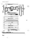
Multiplex control sends off-hook signaling data to CE on the data
input bus during time slot 0.
(6)
CE detects signaling.
(7)
ztt
ymoves
ringing signaling on the data output bus during time
5.08 Talking Connection.
(1) Circuit and codec enable inputs are received during message time
slot assigned by CE.
(2)
During message time slot, digital voice on the data output bus is
applied to the telephone via multiplex control, PCM
codec,
digital-to-analog filter and hybrid transformer.
(3)
During message time slot, analog voice from telephone is applied to
the data input bus via hybrid transformer, analog-to-digital filter,
PCM codec, multiplex control and buffer.
. .
5.09 Terminating the Call.
(1)
(2)
(3)
(4)
(5)
(6)
Called telephone goes on-hook.
On-hook condition detected by off-hook detector.
No signaling on the data input bus during time slot 0.
_-
CE detects removal of signaling.
Signaling for line circuit is removed from data output bus.
Circuit enable inputs removed (message time slot is no longer
assigned to line circuit
0).
(7)
Circuitry in ‘idle’ condition, ready for next call.
MESSAGE WAITING
LAMP OPERATION
5.10 Message Waiting Lamp Activation.
(1)
Telephone idle.
(2)
CE receives a signal from the message center and sends it to the
message waiting line circuit.
(3)
The message waiting lamp control on the message waiting line
circuit places
-150 V across tip and ring to light the lamp at the
telephone and -48 V
accross
-48 V and GND pair to the lamp
bank.
(4)
Telephone goes off -hook.
Page 5-3
.
.


