


2-2 Definitions
through the I/O panels or EM1 filters. In addition, all vertical routing of the
internal signal cables should be done on the right side of a column.
The InterGroup UEM should be located at the top of a column and adjacent
to the CE UEMs.
Peripheral Equipment (PE or IPE) UEMs may be located away from CE and
CPU
UEMs
by a maximum network cable length of 45 feet. This means
that typically at floor level the CE UEM serving its PE cannot be more than
20
feet apart.
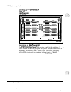
Configurations
A full network group consists of two half network group
UEMs
stacked one
on top of the other. This rule does not apply when the Network Module is
used only as a DTI/PRI shelf.
SL-1 Option 51 can be configured using one Network Module (half network
group) or two Network Modules (full network group). SL-1 Option 71 must
be expanded in increments of full network groups.
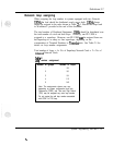
In multiple-group machines, the addition of network groups should be
considered in the floor plans. Make sure the network groups are located in
one contiguous equipment bay. One possibility is to provide space for
expanding network groups to the left of CPU
UEMs
and Peripheral
---
Equipment (PE or IPE) to the right of CPU UEMs.
Another possibility is to
keep Peripheral Equipment (PE or IPE) expansion as a separate bay. See
Figure 14 “Option 71 with multiple network group.”
System engineering 553-3001-151
I
v