


42 Planning the site
-
Storage cabinets for spare parts, backup tapes or disks, and printer
Paper
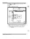
The floor plan
Since the space requirements and the overall layout of the equipment room
can have an effect on the installation, operation, and maintenance of a
system, a detailed floor plan should be drawn up for each site.
...>.;,.%
The floor plan should show the location of utility closets and cross- connect
terminals. All cables running from distribution points to the zones should
be clearly designated with the zone ID. The zones are typically the
termination point of conduits throughout the office. (See Figure 8 “Sample
building cable plan” for an illustration of zones.) Within a zone the cables
should be identified by their number within the zone.
Note:
According to the National Fire Code, equipment must be
located at least 12 inches from a sprinkler head. If your system has
.-
four
UEMs
and a cable rack, do not place the equipment directly under
any sprinkler heads.
Consider the following guidelines when planning the equipment room floor
plans:
-
a recommended minimum ceiling height of 8 ft (2436mm) or greater
---
-
a minimum distance between equipment aisles of 30 inches (760mm)
-
a minimum distance between end of aisle stacks and wall and between
rows of 3 ft (914mm)
-
location of modems, printers, and terminals
-
size and location of reserve power
-
size and location of cross-connect terminal
-
size and location of maintenance/technician area
-
number of rows and future expansion needs
(RF’E
or Meridian Mail, for
example). Refer
to System engineering
(553-3001-151) for guidelines
on system expansion.
.
;
. . .
.>
-4
<;?I
$7
Installation planning 553-3001
-I20
.
.