


34020113EN/AA - Page 13
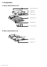
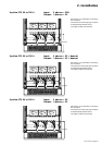
PEN
N
PE PEN
S1 S2
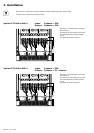
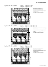
N L1 L2 L3 N L1 L2 L3 N L1 L2 L3
PE
N
PE PE
NN
S1 S2
N L1 L2 L3 N L1 L2 L3 N L1 L2 L3
PE PE PE
S1 S2
N L1 L2 L3 N L1 L2 L3 N L1 L2 L3
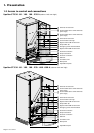
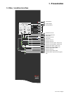
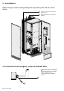
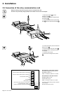
2. Installation
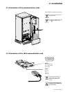
See section 1.3 for information on accessing
the connections.
Connections are made using lugs connected
to threaded studs (diameter 8 mm).
The cables are tied to the earth bar.
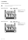
See section 1.3 for information on accessing
the connections.
Connections are made using lugs connected
to threaded studs (diameter 8 mm).
The cables are tied to the earth bar.
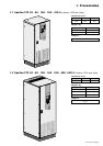
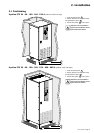
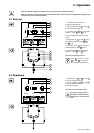
Upsilon STS 30 to 250 A Input: 3 phases + PE + Neutral
Output: 3 phases + PE + Neutral
275 mm
275 mm
See section 1.3 for information on accessing
the connections.
Connections are made using lugs connected
to threaded studs (diameter 8 mm).
The cables are tied to the earth bar.
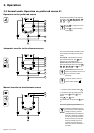
275 mm
Upsilon STS 30 to 250 A Input: 3 phases + PEN
Output: 3 phases + PE
Upsilon STS 30 to 250 A Input: 3 phases + PE
Output: 3 phases + PE