


34020113EN/AA - Page 5
Contents
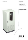
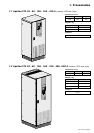
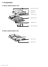
1. Presentation
1.1 Upsilon STS 30 - 60 - 100 - 160 - 250 A (cabinet 1400 mm high).............................................. 7
1.2 Upsilon STS 30 - 60 - 100 - 160 - 250 - 400 - 600 A (cabinet 1900 mm high) .......................... 7
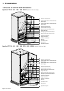
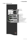
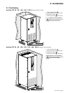
1.3 Access to control and connections .......................................................................................... 8
Upsilon STS 30 - 60 - 100 - 160 - 250 A (cabinet 1400 mm high) ................................................. 8
Upsilon STS 30 - 60 - 100 - 160 - 250 - 400 - 600 A (cabinet 1900 mm high)............................... 8
1.4 Man / machine interface ............................................................................................................... 9
1.5 Relay communication card ........................................................................................................ 10
1.6 JBus communication card ......................................................................................................... 10
2. Installation
2.1 Positioning .................................................................................................................................. 11
Upsilon STS 30 - 60 - 100 - 160 - 250 A (cabinet 1400 mm high) ............................................... 11
Upsilon STS 30 - 60 - 100 - 160 - 250 - 400 - 600 A (cabinet 1900 mm high)............................. 11
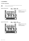
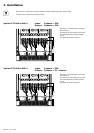
2.2 Power connections ..................................................................................................................... 12
Upsilon STS 30 to 250 A with input/output: 3 phases + PEN, ..................................................... 12
Upsilon STS 30 to 250 A with input: 3 phases + PEN, output: 3 phases + PE + Neutral ............ 12
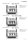
Upsilon STS 30 to 250 A with input: 3 phases + PEN, output: 3 phases + PE ............................ 13
Upsilon STS 30 to 250 A with input/output: 3 phases + PE + Neutral ......................................... 13
Upsilon STS 30 to 250 A with input/output: 3 phases + PE ......................................................... 13
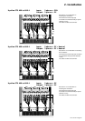
Upsilon STS 400 to 600 A with input/output: 3 phases + PEN .................................................... 14
Upsilon STS 400 to 600 A with input: 3 phases + PEN, output: 3 phases + PE + Neutral .......... 14
Upsilon STS 400 to 600 A with input: 3 phases + PEN, output: 3 phases + PE .......................... 15
Upsilon STS 400 to 600 A with input/output: 3 phases + PE + Neutral ....................................... 15
Upsilon STS 400 to 600 A with input/output: 3 phases + PE ....................................................... 15
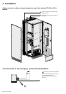
Cable running for cables entering through the top of the Upsilon STS 30 to 250 A cabinet ........ 16
2.3 Connection of the emergency power off terminal block......................................................... 16
2.4 Connection of the communication cards ................................................................................. 17
2.5 Connection of the JBUS communication card......................................................................... 17
2.6 Connection of the relay communication card.......................................................................... 18
3. Operation
3.1 Start-up ........................................................................................................................................ 19
3.2 Shutdown..................................................................................................................................... 19
3.3 Normal mode: operation on preferred source S1 .................................................................... 20
Operation on the preferred source................................................................................................ 20
Automatic transfer to the alternate source .................................................................................... 20
Manual transfer to the alternate source ........................................................................................ 20
Manual transfer to an out-of-phase alternate source .................................................................... 21
3.4 Display screens........................................................................................................................... 22
3.5 Upsilon STS customization........................................................................................................ 23
3.6 Customization of the relay communication card..................................................................... 24
4 Maintenance
4.1 Identification of anomalies......................................................................................................... 25
4.2 Transfer to the manual bypass .................................................................................................. 25
5 Environment .....................................................................................................................................26