


34020113EN/AA - Page 19
Q1BP
Q1 Q2
Q2BP
Q3
S1 S2
Q1 Q5 Q6 Q2
Q1BP Q2BPQ3
0
1
0
1
000
111
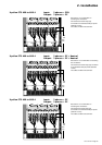
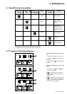
3. Operation
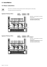
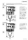
3.1 Start-up
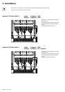
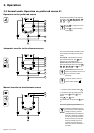
3.2 Shutdown
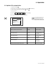
1 - Check that the two sources are
energised (voltage present).
2 - Set circuit breakers Q5 2 and Q6 3
to the ON position (position 1).
3 - Turn switch Q1BP 6 to the ON position
(position 1). LEDs 37 and 38 go on.
The load is supplied by Source 1 via the
bypass.
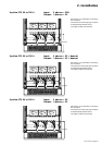
4 - Set switches Q1 1 and Q3 7 to the
ON position (position 1). LEDs 29 , 31 ,
and 36 go on.
5 - Turn switch Q1BP 6 back to the OFF
position (position 0). LED 37 goes off.
6 - Set switch Q2 4 to the ON position
(position 1). LEDs 30 and 32 go on.
The load is supplied by Source 1.
If LED 33 is red or off, if LEDs
31 and/or 32 are orange or
red: see section "Maintenance".
1 - Set switches Q1 1 , Q2 4 and Q3 7
to the OFF position (position 0).
2 - Set circuit breakers Q5 2 and Q6 3
to the OFF position (position 0).
All LEDs should go off.
The load is not supplied with power.
Dangerous voltage levels are
still present inside the Upsilon
STS cabinet, in the connection
zone.
1
2
3
4
6
7
1
2
3
4
7
Q1 Q5 Q6 Q2
Q1BP Q2BPQ3
0
1
0
1
000
111
29
30
31
32
33
36
37
38
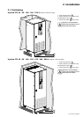
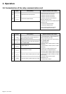
Make sure that the voltages and frequencies of the two sources S1 and S2 are identical.
Make sure that the voltages of the two sources S1 and S2 are the same as the rated voltage (400 V) of Upsilon STS,
otherwise see section 3.5 (Customization).
Q1BP
Q1 Q2
Q2BPQ3
S1 S2