


Page 18 - 34020113EN/AA
1
2
3
4
5
6
A
B
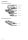
2. Installation
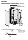
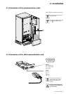
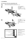
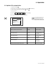
2.6 Connection of the relay communication card
1 - Remove the screws 41 and the
protection cover 43 .
2 - Run the communication cables through
the openings 44 .
3 - Connect the cables to the input terminal
block 46 and the output terminal block 45 .
4 - Put the cover back in place and secure it
with the screws 41 .
5 - Secure the cables using the screws 47 .
6 - Note the position of the power sources
on the labels.
7 - Insert the card in its slot.
8 - Secure the card using the two screws
42 .
46
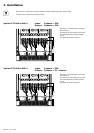
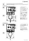
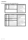
Characteristics of the output contacts:
Permissible voltage: 250 V AC, 30 V DC
Permissible current: 2 A
Cable: 4 x 0.93 mm
2
, Ø 6.6 mm ± 0.3 mm.
Characteristics of the input contacts:
Switched voltage: 5 V DC
Current drawn: 10 mA
Cable: 4 x 0.34 mm
2
, Ø 5 mm ± 0.5 mm.
41
42
47
42
Before proceeding, disconnect all power sources connected to the card.
Do not mix very low safety voltage (VLSV) and non-VLSV circuits on the card outputs.
43
45
44
6
5
4
3
2
1
BA
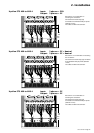
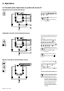
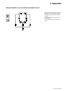
Source S2 status condition (active or inactive)
Source S1 status condition (active or inactive)
Overload status condition
STS fault
General alarm
(fault on one of the sources or on the STS)
Load-supplied status condition
(presence or absence of power to the load)
Command to disable transfer (transfer to alternate
source inhibited)
Memorised faults reset command