


34020113EN/AA - Page 17
JBUS/MODBUS
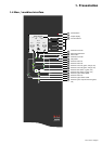
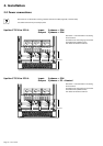
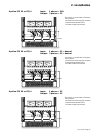
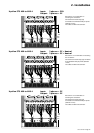
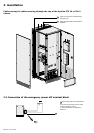
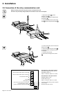
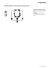
2. Installation
2.4 Connection of the communication cards
Tie the cables to the cable way on the door.
Do not run the control wires with
the power cables.
Two slots are available in the card
cage 5 for additional cards.
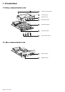
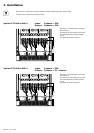
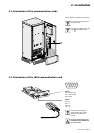
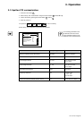
2.5 Connection of the JBUS communication card
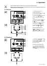
RS232:
Pin 2: Rxd (or Txd)
Pin 3: Txd (or Rxd)
Pin 5: Earth
RS485:
Pin 4: R-
Pin 5: T-
Pin 8: R+
Pin 9: T+
For information on using the
communication card, see the
JBUS communication card
manual.
Only one communication port
(the RS232 OR the RS485) may
be used at a time.
5
12345
6789