


34020113EN/AA - Page 15
N
PEN
PE PEN
S1 S2
N L1 L2 L3 N L1 L2 L3 N L1 L2 L3
PE PE PE
NN N
S1 S2
N L1 L2 L3 N L1 L2 L3 N L1 L2 L3
PE PE PE
S1 S2
N L1 L2 L3 N L1 L2 L3 N L1 L2 L3
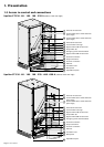
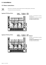
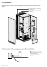
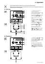
2. Installation
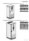
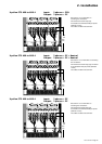
Upsilon STS 400 to 600 A Input: 3 phases + PE + Neutral
Output: 3 phases + PE + Neutral
See section 1.3 for information on accessing
the connections.
Connections are made using lugs connected
to two threaded studs per phase (diameter
10 mm).
The cables are tied to the earth bar.
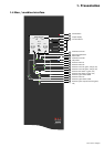
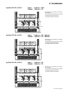
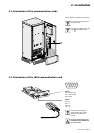
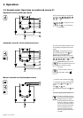
See section 1.3 for information on
accessing the connections.
Connections are made using lugs
connected to two threaded studs per phase
(diameter 10 mm).
The cables are tied to the earth bar.
463
mm
403
mm
463
mm
403
mm
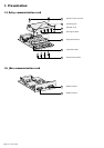
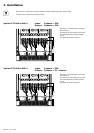
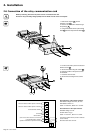
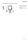
See section 1.3 for information on
accessing the connections.
Connections are made using lugs
connected to two threaded studs per phase
(diameter 10 mm).
The cables are tied to the earth bar.
463
mm
403
mm
Upsilon STS 400 to 600 A Input: 3 phases + PEN
Output: 3 phases + PE
Upsilon STS 400 to 600 A Input: 3 phases + PE
Output: 3 phases + PE