


163
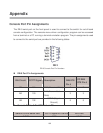
make sure the power pair it uses. The following table is the signal power pair RJ-45
port pinout.
Pin Signal / Name
1 RX+ / VCC -
2 RX- / VCC -
3 TX+ / VCC +
4 NC
5 NC
6 TX- / VCC +
7 NC
8 NC
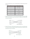
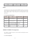
When the PD device pin out is in MDI mode without bridge circuit function, please
use the crossover cable for power and data transmit. Please refer to the above table
for the pin out transform.
(VCC-)1 1 (VCC+)
(VCC-)2 2(VCC+)
(VCC+)3 3(VCC-)
(VCC+)6 6(VCC-)
MDI-X MDI w/o bridge circuit
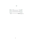
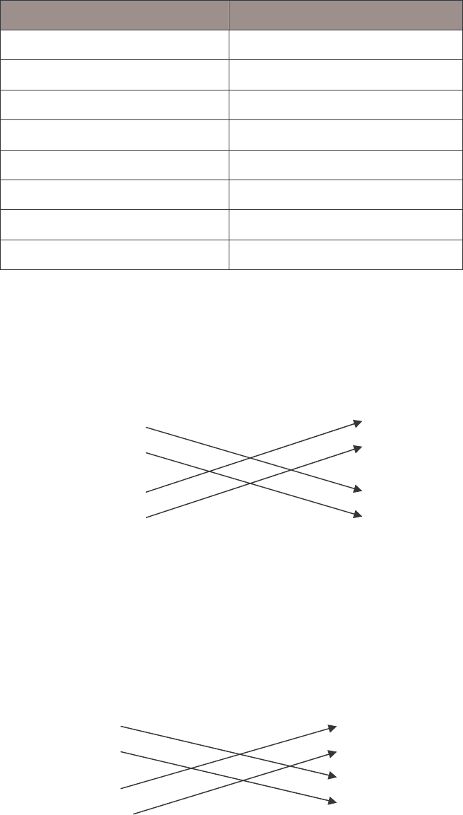
When the PD device is in MDI mode with bridge circuit function, the straight forward
and crossover cable both workable for power and data transmit. Please refer to the
above table for the pin out antithesis.
(VCC-)1 1 (VCC+)
(VCC-)2 2(VCC+)
(VCC+)3 3(VCC-)
(VCC+)6 6(VCC-)
MDI-X MDI w/ bridge circuit