


2
-
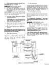
2.
GAS/CURRENT
SENSING
CONTROL
CON
-
NECTIONS
(Figures
2-1
And
2-2)
N-.
ELECTRIC
SHOCK
can kill.
•
Do
not
touch
live electrical
parts.
•
Shut
down
unit,
welding
power
source,
and
robot, and
disconnect
input
power
employing
“lockout/tagging
procedures”
before
making
in
-
terconnections.
Lockout/tagging
procedures
consist
of
padlocking
line
disconnect
switch
in
open
position,
removing
fuses
from fuse
box,
or shutting
off
and
red-tagging
circuit
breaker
or
other disconnecting
device.
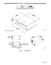
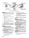
A.
Computer
Interface
-
Gas/Current
Sensing
Control
Connections
1.
Align
keyways,
insert 14-pin
Amp
plug into
mat
-
ching
receptacle
on
computer
interface,
and
rotate threaded
collar
fully
clockwise.
2.
Align
keyways,
insert
16-pin
Amp
plug
into
mat-
ching
receptacle
on
gas/current
sensing
control,
and
rotate threaded
collar
fully
clockwise.
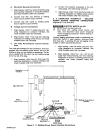
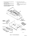
B.
Gas/Current
Sensing
Control
-
Motor
Con
-
nections
Align
keyways,
insert
14-pin
plug
from
motor
into
mat-
ching
receptacle
on
gas/current
sensing
control,
and
rotate threaded
collar
fully
clockwise.
C.
Weld
Cable
Connections
Route
cable
from
welding
power
source
positive
weld
output
terminal,
through
the
gas/current
sensing
con
-
trol, to
the
wire
drive
assembly
and
connect
cable
to
weld
cable
terminal
(see
Motor/Drive
Assembly
Owner’s
Manual
for
location).
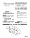
D.
Gas
Connections
Connect
hose
from
gas
regulator/flowmeter
(customer
supplied)
at
gas
source
to IN fining
on
gas/current
sen
-
sing
control.
Connect
gas
hose from
wire
drive
assembly
to
fitting
on
gas/current
sensing
control.
The
gas
flow
must
be
accurately
controlled by
a
regulator/flowmeter
at
the
source.
E.
Touch
Sensor Connections
Connect
cord with
two
friction
connectors
coming
from
gas/current
sensing
control
to
touch
sensor
leads
com
-
ing
from
outlet cable. Polarity
is
not
important
for
this
connection.
2
-
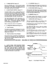
3.
COMPUTER
INTERFACE
-
WELDING
POWER
SOURCE
CONNECTIONS
(Figures
2-1
And
2-2)
ELECTRIC
SHOCK
can kill.
•
Do
not
touch
live electrical
parts.
•
Shut
down
unit,
welding
power
source,
and
robot, and
disconnect
input
power
employing
“lockout/tagging
procedures”
before
making
in
-
terconnections.
Lockout/tagging
procedures consist
of
padlocking
line
disconnect
switch
in
open
position,
removing
fuses
from
fuse box,
or
shutting
off
and
red-tagging
circuit
breaker
or
other disconnecting
device.
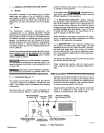
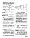
There
are several
cords
used
for
interconnections
bet
-
ween
the computer
interface
and
welding
power
source.
Examine
and
select
the
proper
cord
for
the
following
connections.
115
Volts
AC/Contactor
control
Cord
Computer
Interface
RC17
Rd
Arc
Failure
Connection
In
Robot
Control
UnIt
Arc
Pak
Welding
Power
Source
Sensor
GaslCurrent
Sensing
Control
Motor
Control-
Cord
TB-i
14
357
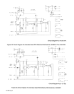
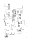
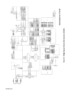
Figure
2
-
2.
Interconnection
Diagram
OM-882
Page
3