


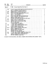
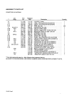

Part
No.
Description
Quantity
Figure
D
109
936
Control
Box,
Gas/Current
Sensor
047
497
+079
682
079
687
109
021
049 455
010
610
010 494
057 358
010 604
602 934
079
573
079
574
047
637
079
534
109 938
038
081
109
561
090 246
079 535
2
LABEL,
general
precautionary
WRAPPER
RELAY,
current
CASE
SECTION,
bottom/front/sides
CORD,
No.
182/c
(order
by
ft)
CONNECTOR,
clamp-cable
1/2
inch
BUSHING,
snap
1-3/8
ID
x
1-3/4
mtg
hole
BUSHING,
snap
ID
x
1
.37
mtg
hole
FITTING,
hose-brassbushing
1/4
NPTx5/8-18
FITTING,
pipe-coupling
1/4
NPT
FITTING,
pipe-nipple
L
1/4
NPT
x
6
BRACKET,
mtg-component
HOUSING
RECEPTACLE
&
SOCKETS
(consisting
of)
•
TERMINAL,
female
DIODE,
1
amp
400
volts
SP
BLOCK,
terminal
20
amp
4
pole
VALVE,
24
volts dc
2
way
1/4
IPS
port
1/8
orifice
RECEPTACLE
W/PINS
(consisting
of)
•
TERMINAL,
male
1
1
1
1
2ft
1
2
2
2
1
1
2
1
14
1
9
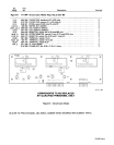
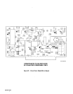
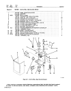
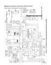
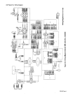
TC-109
Lao
Figure
D
-
Control
Box,
Gas/Current
Sensor
+
When
ordering
a
component
originally displaying
a
precautionary
label,
the
label
should
also
be
ordered.
BE
SURE
TO
PROVIDE
MODEL
AND
SERIAL
NUMBER
WHEN
ORDERING
REPLACEMENT
PARTS.
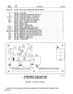
OM-882
Page
13
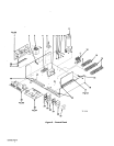
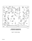
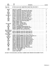
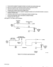
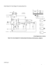
Item
Dia.
No.
Mkgs.
1
2
3
4
5
6
7
8
9
10
11
12
13
REED
RC7
14
D2
15
4T
16
GS1
17
RC16
67
8
1