


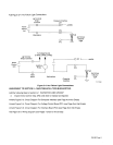
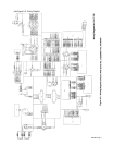
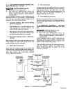
B.
ARC
FAILURE
Light
Connections
(Figure 2-4)
A
WARNING:
Read
and
follow safety Information
at
beginning
of Section
2-5
before
proceeding.
The ARC FAILURE
light
orlthe
computerinterface front panel
is
turnedon
and
off
by a
signalfromthe
robot control
unit.
Locate
supplied
length
of
18
gauge/2-conductor cord
for
this
connection,
and
proceed
as
follows:
1.
For
robot control
units
with
no
other
connections
at
jig
terminal
strip
2:
a.
Open
robot control
unit
door,
and
locate
jig
terminal
strip
2.
b.
Route
cord under
cross member
below
door.
c.
Make cord connections
to
terminal
strip
common and
the Weld Alarm
terminal.
d.
Close
robot control
unit
door,
and
route cord
through strain
relief on
rear
panel
of
computer
interface.
e.
Connect
cord
to
2TF
and
2TG.
2.
For
robot control
Units
when
115
or
24 vac,
or
24
vdc
is
used
at
jig terminal
strip
2T:
a.
Obtain
a
115
or
24
vac,
or
24
Vdc
isolation
relay,
and install
into
jig
interface.
b.
Open
robot control
unit
door,
and
locate
jig
terminal
strip
2.
c. Route
customer supplied
18
gauge/2-conductor cord under
cross member
below
door.
d.
Make
cord connections
to
terminal
strip
common
and
the
Weld Alarm
terminal.
e.
Close
robot control
unit
door,
and
route
cord
to
jig
interface.
f.
Connect
cord
to
isolation
relay
coil
and
voltage source.
g.
Cut
off
terminals from
one end of
supplied
18
gauge/2-conductor
cord,
and
install terminals
to
connect
to
contacts
on
isolation
relay.
h.
Connect
one end of
cord
to
a
set
of
normally-open
contacts
on
isolation
relay.
i.
Route cord
through strain
relief on
rear
panel
of
computer interface.
j.
Connect
cord
to
2TF
and
2TG.
OM-882 Page
2