


Add
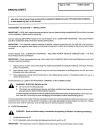
Figure
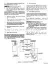
2-4.
Arc
Failure Light
Connections
Jig
Terminal
Strip
2
Common
Robot
control
Unit
weld
Alarm
Robot
Control
Unit
Computer
Interface
2TF
+24VDC
2TG
2TL
Arc
Failure
Indicator
Light
To Voltage
Source
(115VAC, 24VAC,
24VDC)
-rj 2TF ~—
Arc
Failure
Indicalor
Light
TA-il5
648
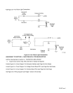
Figure
2-4. Arc
Failure
Light
Connections
AMENDMENT
TO
SECTION
5-
MAINTENANCE
&
TROUBLESHOOTING
Add the
following Step
to
Section
5-1
-
INSPECTION
AND
UPKEEP
3.
Inspect
motor
control
relay,
CR2,
and
clean
or
replace
as
required.
Amend
Figure
5-3.
Circuit
Diagram
For
Computer
Interface
(see
Page
4
on
this
Errata)
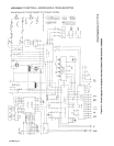
Amend
Figure
5-4.
Circuit
Diagram
For
Voltage
Control
Board
PCi
(see
Page
5
on
this
Errata)
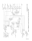
Amend
Figure
5-6.
Circuit Diagram
For
Interface
Board PC3 (see
Page
6
on
this
Errata)
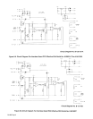
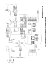
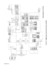
Add
Figure
5-9.
Wiring Diagram
(see
Pages
7
and
8
on
this
Errata)
Weld
Alarm
Jig
Interface
OM-882
Page
3