


ERRATA
SHEET
AMENDMENT
TO
SECTION
2—
INSTALLATION
A
WARNING: ELECTRIC
SHOCK
can
kill.
0
Do
not
touch
live
electrical
parts.
A.
CVICC
Connections
A
1.
Locate
terminal
Strip
2T.
May
31,1990
~OM.882j
After
this
manual
was
printed,
refinements
In
equipment
design
occurred.
This
sheet
lists
exceptions
to
data
appearing
later
in
this
manual.
IMPORTANT:
A
25
ft.
(8m)
interconnecting
cord
with
a
five-pin
Amphenoiplug
is
supplied
with
this
unit
but
is
not
used
in
this
installation. Retain
cord
for
future
use.
Add the
foliowing
IMPORTANT
block
to
the
end of Section
2-3A.
COMPUTER
INTERFACE
-
WELDING
POWER
SOURCE
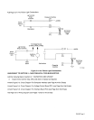
CONNECTIONS: Wire
Stick Sensing
Connections
IMPORTANT:
If dc
electrode
negative
welding
is
desired,
reverse connections so
the
lead
with
ring
terminal
is
connected
to
the
negative
weld
output
terminal
and
the
lead
with
a
clamp
is
connected
to
the
positive
weld
output
terminal.
Amend
Section
2-3C.
COMPUTER
INTERFACE
-
WELDING
POWER
SOURCE
CONNECTiONS:
115
Volts
AC/Contactor Control
Connection
IMPORTANT:
Cords
are
supplied
that
may
not
be used
in this
installation.
Match
cord
to
welding
power
source
and
computer
interface
available.
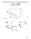
1.
Align
keyways,
insert
4-socket
Amp
plug
into
matching
receptacle
on
computer
interface,
and rotate
threaded
collar
fully clockwise.
2.
Align
keyway,
insert
14-pin
Amphenol
plug
into
matching
receptacle
on
welding
power
source,
and
rotate
threaded
collar fully
clockwise.
3.
Place
appropriate
remote control switch(es)
on
the
welding
power
source
in
the
proper
position
for
use
of
a
remote control
device.
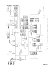
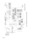
Amend
Section 2-5.
COMPUTER
INTERFACE
TERMINAL
STRIP
CONNECTIONS
0
Shut
down unit,
welding
powersource, and
robot,
and
disconnect
input
power
employing
locko
ut/tag
-
ging
procedures
before
making
interconnections.
Lockout/tagging
procedures
consist
of
padlocking
line
disconnect
switch
in
open
position, removing fuses
from
fuse box,
or
shutting
off
and
red-tagging
circuit
breaker
or
other
disconnecting
device.
There
are
several
terminal
strips
inside the
computer
interface
for
control
connections. Remove
unit
top
cover,
loosen
screws
on
strain
relief
on
unit
rear
panel
if
necessary,
and
locate
appropriate terminal
strip
for
connections.
Tighten
screws
on
strain
relief
if
necessary,
and reinstall
top
cover
when
procedure
is
finished.
WARNING:
Read
and
follow
safety
information
at
beginning of Section
2-5
before
proceeding.
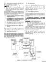
2.
For
CC
operation,
remove
jumper
link
between
terminal
E
and
F
on
2T.
IMPORTANT:
The
Inductance control
is
disabled
when operating
in
the
CC
(constant
current)
mode.