


3
-
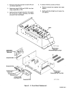
1.
POWER
SWITCH
(Figure
3-1)
3
-
4.
VOLTMETER
(Figure
3-1)
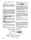
Placing
the
POWER
switch
in
the
ON
position
applies
input
power
to
the interface.
The
interface
must
be
on
for
the
robot
to
weld.
Placing
the
POWER
switch
in
the
OFF
position
shuts down
the interface.
3
-2.
INDUCTANCE
CONTROL
(Figure
2-1)
The
INDUCTANCE
control
is
a
digital
pushbutton
con
-
trol
which
can
be
set
for
inductance
levels
1
through
7.
As
the
level
of
inductance
increases,
the
rate of
change
of
the
weld
output
or
speed
of
response
slows
down.
The
slower
response
time
produces
a
softer
arc,
more
fluid
welding
puddle,
and
flatter,
smoother
bead.
The
0
(zero)
setting gives
minimum
inductance,
i.e.,
a
stiff,
fast-responding
arc, and
a
small,
fast-freezing
puddle.
The
7
setting
gives
maximum inductance
characteristics,
i.e.,
a
soft,
slow-responding,
low
spat-
ter
arc, and
high
weld
puddle
fluidity.
Select
a
setting
best
suited
for
the
application.
3
-
3.
OVERLOAD
PROTECTION
(Figure
3-1)
A.
Fuse
Protection
The
interface
is
protected
from
damage
due
to
an
inter
-
nal
short
or
excessive
overload by fuse
Fl.
If
fuse
Fl
opens,
the
interface
shuts
down.
See
Section
5-2
for
replacement
procedures.
B.
Wire
Drive
Motor
Circuit
Breaker
The
wire
drive
motor
is
protected
from
damage
due to
overload
by
circuit
breaker
CB1. If
CB1
opens,
the
inter-
face
shuts
down.
Manually
depress
the
reset
button
to
reset
the
circuit
breaker.
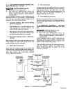
The
voltmeter
displays
weld
voltage
to
the
nearest tenth
of
a
volt while
welding
and preset
voltage
while
idling.
3
-5.
WIRE
SPEED
METER
(Figure
3-1)
The
wire
speed
meter
displays
preset
wire
feed
speed
to
the
nearest
inch
per
minute while
welding
and
idling.
Actual
and preset
wire
feed speed
are
the
same
due
to
the
wire
feed
speed
feedback
circuit.
3
-
6.
AMMETER
(Figure
3-1)
The
ammeter
displays
weld
amperage
to
the
nearest
amp
while
welding
and preset
amperage
while
idling.
3
-
7.
INDICATOR
LIGHTS
(Figure
3-1)
There
are
five
indicator
lights
on
the interface.
These
are
visual
indications
of
various
process
functions.
The
GAS
light
turns
on
when
the
gas
valve
is
energized
to indicate
shielding
gas
flow.
The
CONTACTOR
light
turns
on
when
the
welding
power
source
contactor
is
energized
to indicate that
weld
output
is
available.
The
WIRE
FEED
light
turns
on
when
the
wire
drive
motor
is
energized
to indicate that
wire
is
feeding.
The
CURRENT
light
turns
on
when
the
current
detect
relay
is
energized
to indicate that
an
arc
is
established.
The
ARC
FAILURE
light
turns
on
when there
is
an
arc
outage while
welding.
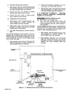
SECTION
4
-
SEQUENCE
OF
OPERATION
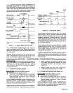
Arc
Initiation
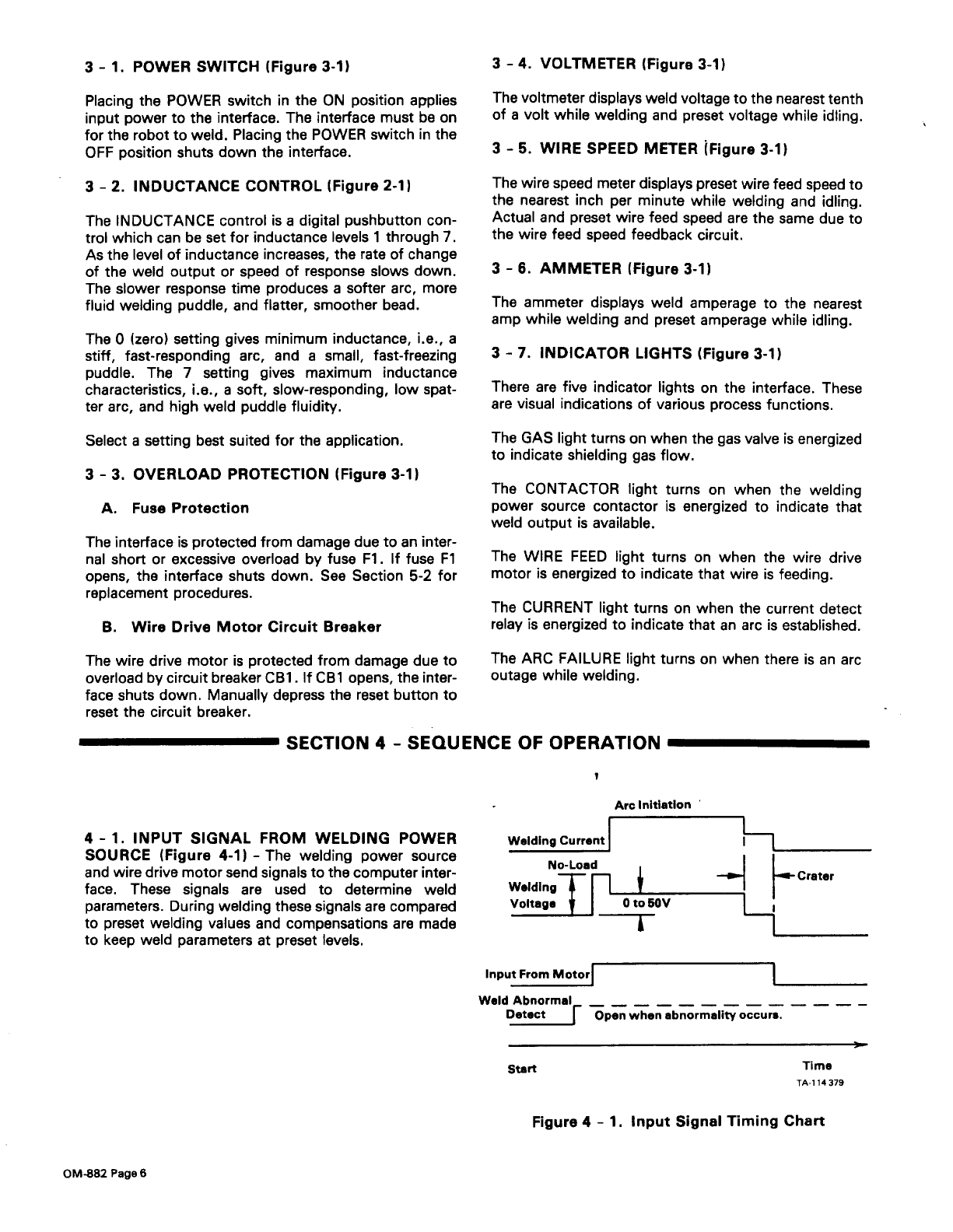
4
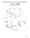
-1.
INPUT
SIGNAL
FROM
WELDING
POWER
SOURCE
(Figure
4-1)
-
The welding
power
source
and
wire
drive
motor
send
signals
to
the
computer
inter-
face.
These
signals
are
used
to
determine
weld
parameters.
During
welding
these
signals
are
compared
to
preset
welding
values
and
compensations
are
made
to
keep
weld
parameters
at
preset
levels.
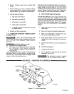
Welding
Current
No-Load
WeldingT~
Voltage
0
to 50V
—F
WeldAbnormal
—
D~LY
Open when
abnormality
occurs.
Start
Time
TA-i
14
379
Figure
4
-
1.
Input
Signal
Timing
Chart
H-
Crater
OM-882
Page6