


ERRATA
SHEET
After
this
manual
was
prInted,
refinements
In
equipment
design
occurred.
This
sheet
lists
exceptIons
to
data
appearing
later
in
this
manual.
AMENDMENT
TO
SECTION
2
-
INSTALLATION
IMPORTANT:
A
25
ft.
(8m)
interconnecting
cord
with
a
five-pin
Amphenoiplug
is
supplied
with
this
unit
but
is
not
used
in this
installation.
Retain
cord
for
future
use.
Amend
Section
2-5.
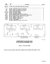
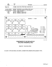
COMPUTER
INTERFACE
TERMINAL STRIP CONNECTIONS
A
WARNING: ELECTRIC
SHOCK
can
kill.
•
Do
not
touch
live
electrical
parts.
•
Shut
down
unit,
welding
power
source,
and
robot,
and
disconnect
input
power
employing
locko
ut/tag
-
ging
procedures
before
making
interconnections.
Lockout/tagging
procedures consist
of
padlocking
line
disconnect
switch
in
open
position,
removing
fuses
from
fuse
box,
or
shutting
off
and
red-tagging
circuit
breaker
or
other
disconnecting
device.
There
are
several
terminal
strips
inside the computer
interface
for
control
connections.
Remove
unit
top
cover,
loosen
screws
on
strain
relief
on
unit
rear
panel
if
necessary, and
locate
appropriate
terminal strip
for
connections.
Tighten
screws
on
strain
relief
if
necessary,
and
reinstall
top
cover
when procedure
is
finished.
A.
CV/CC Connections
A
WARNING:
Read
and
follow
safety
information
at
beginning of
Section
2-5
before
proceeding.
1.
Locate
terminal
strip
2T.
2.
For
CC
operation, remove
jumper
link
between terminal
E
and
F on
2T.
IMPORTANT:
The
Inductance
control
is
disabled
when
operating
in
the
CC
(constant
current)
mode.
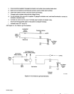
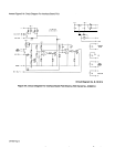
B.
ARC
FAILURE
Light Connections
(Figure
2-4)
A
WARNING:
Read
and
follow
safety
information
at
beginning of
Section
2-5
before
proceeding.
The ARC
FAILURE
light on
the
computer
interface
front
panel
is
turned
on
and
off
by a
signal
from
the
robot
control
unit.
Locate
supplied
length
of
18
gauge/2-conductor
cord
for
this
connection,
and
proceed
as
follows:
1.
For
robot
control units
with
no
other
connections
at
jig
terminal strip
2:
a.
Open robot
control
unit door, and locate
jig
terminal strip
2.
b.
Route
cord
under
cross
member
below
door.
c.
Make
cord
connections
to
terminal strip common
and
the
Weld
Alarm
terminal.
d.
Close
robot
control
unit door,
and
route
cord
through
strain
relief
on
rear
panel
of
computer
interface.
e.
Connect
cord
to
2TF
and
2TG.
2.
For
robot
control units
when
115
or
24
vac,
or
24
vdc
is
used
at
jig
terminal strip
2T:
a.
Obtain
a
115
or
24
vac,
or
24
vdc
isolation
relay,
and install
into
jig
interface.
b.
Open
robot
control
unit
door,
and
locate
jig
terminal
strip
2.
-v