


4
-
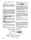
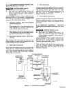
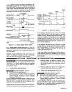
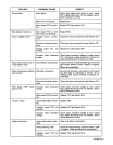
2.
OUTPUT
SIGNALS
FROM
COMPUTER
IN
-
TERFACE
(Figure
4-2)
-
The
interface
interprets
the
input
signals
from
the
welding
power
source,
wire
drive
motor,
robot,
and
wire
stick
check
circuit.
The
output
of
the
computer
interface
regulates the
welding
power
source
and
wire
feed
functions
while
welding.
Wire
Start
Relay
Arc
Initiation
Open
Close
I I
1OVDC
5VDC
2.5VDC
I
Voltage
1
.25VDC
I I
Command
TA-i
14
378
Figure
4
-
2.
Output
Signal
Timing Chart
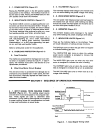
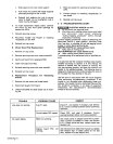
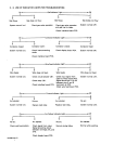
4
-
3.
WIRE
STICK
CHECK
(Figure
4-3)
-
After
the
weld
is
completed,
the
wire
stick
check
is
performed
to
determine
if
the
welding
wire
has
burned
back
out
of
the
weld
puddle.
Feedback
is
used
to
determine
if
the
wire
is
free of
the
weld.
If
the
feedback
indicates
the
wire
is
free of
the
weld,
the
robot
can
cycle
to
its
next
sequence.
If
the
feedback
indicates
the
wire
is
stuck,
the
welding
power
source
is
sent
a
1
.25
VDC
command
signal
to
provide
minimum welding
power
source
output.
The
contactor
is
pulsed
on.
If
the
wire
was stuck,
the
pulsed
voltage
should
be
enough to free
the wire.
Feedback
is
used
to
determine
if
the
wire
is
now
free of
the
weld.
If
the
feedback
indicates
the
wire
is free,
the
robot
can
cy
-
cle
to
its
next
sequence.
If
the
feedback
indicates
the
wire
is
still
stuck,
a
higher
voltage
command
is given,
and
the
contactor
pulsed
to
free
the
welding
wire.
The
check is performed
and
two
more
voltage
increases
are
used
to
try
and
free
the
welding
wire
(see
Figure
4-3).
If
the
wire
remains
stuck,
the
robot
will
shut down,
a
Weld
Abnormal error
will
be
displayed
on
the
robot
pro
-
gram
module,
and
the
wire
must
be
physically
removed
from
the
weld.
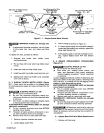
SECTION
5
-
MAINTENANCE
&
TROUBLESHOOTING
•~j~j~~j5
Every
six
months
inspect
the
labels
on
this
unit
for
legibility.
All
precautionary
labels
must
be
maintained
in
a
clearly
readable
state
and
replaced
when
necessary.
See
the
Parts List
forpart
number
of
precautionary
labels.
5
-
1.
INSPECTION
AND
UPKEEP
1.
Repair
or
replace, as
required,
all
hoses,
cords,
and
cables; give
particular
attention
to
frayed
and
cracked insulation
and
areas
where
it
enters
equipment.
2.
Remove grease
and
grime
from
components;
moisture
from
electrical
parts
and
cables.
WARNING:
ELECTRIC
SHOCK
can kill.
•
Do
not
touch live electrical
parts.
•
Shut
down
unit,
welding
power
source,
and
robot
and
disconnect
input
power
employing
‘lockout/tagging
procedures”
before
internally
inspecting
or
servicing.
Lockout/tagging
procedures
consist
of
padlocking
line
disconnect
switch
in
open
position,
removing
fuses
from
fuse box,
or
shutting off
and
red-tagging
circuit
breaker
or
other disconnecting
device.
Usage
and
shop
conditions
will
determine
the
frequency
and
type
of
maintenance.
Inspect
equipment
as
follows:
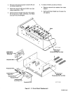
5
-
2. OVERLOAD PROTECTION
(Figure
3-1)
WARNING:
ELECTRIC
SHOCK
can kill.
•
Do
not
touch
live electrical
parts.
•
Shut
down
unit,
welding
power
source,
and
robot
and
disconnect
input
power
employing
“lockout/tagging
procedures”
before
internally
inspecting
or
servicing.
Lockout/tagging
procedures consist
of
padlocking
line
disconnect
switch
in
open
position,
removing
fuses
from
fuse box,
or
shutting off
and
red-tagging
circuit
breaker
or
other disconnecting device.
Close
I
~~chlng~
Open
TA~1
14
379
I I I
Output To
Motor
Figure
4
-
3.
Wire
Stick
Check
Start
OM-882
Page
7