


GUIDE TO INSTALLATION AND OPERATION
6 | Kaleido K2
4 Frame and Electrical Installation
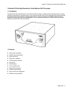
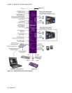
Kaleido is a self-contained unit consisting of a frame, redundant power supplies, a controller card, and various input
and output cards.
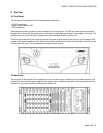
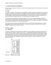
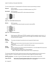
4.1 Frame
The frame is 4 RU high. It incorporates an internal midplane for interconnecting the modules. Modules are installed
from the front of the frame. Each module is associated with input and/or output connectors which are mounted on a
connector panel. These connector panels are installed from the rear of the frame, in the same horizontal position
as their associated module; they also plug into the midplane. The redundant power supplies are installed on the
right of the frame (as viewed from the rear). Their on/off switches are on the rear of the unit.
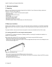
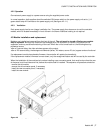
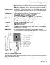
The front panel can be completely removed to give access to the modules. There are two knobs which rotate
toward the top to release the panel. Immediately adjacent to each knob is a screw which blocks the rotation of the
knob. The screws must be removed before the panel can be opened. This provides security against casual access;
their presence has no effect on the functioning of the Kaleido.
The controller module incorporates a master ON/OFF button, and a CPU RESET button. Apertures in the frame
door provide access to these controls when the door is closed. Another aperture allows the controller module’s
POWER LED to be seen when the door is closed.
4.2 Power supplies
4.2.1 Installation
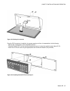
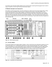
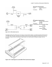
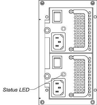
The Kaleido is powered by dual redundant power supplies. These are installed on the left side of the frame (right
side as viewed from the rear – see item 12 on fig. 4.5.1). The supplies are installed and removed from the rear of
the frame. To remove a power supply, release the captive screw at the left side, grasp the folding handle, and pull
the supply straight out of the frame. To install a supply, slide the module into position, and push gently on its front
panel until the connectors are seated and the panel is flush with the frame. Secure it in position with the captive
screw. These supplies are hot-swappable, so that a defective supply may be replaced without removing the
Kaleido from service.
Figure 4.2.1.1 Redundant power supplies