


GUIDE TO INSTALLATION AND OPERATION
4 | Kaleido K2
3 Mechanical Installation
3.1 Unpacking
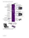
Make sure the following items have been shipped with your Kaleido. If any of these are missing, contact your
distributor or Miranda Technologies Inc.
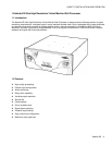
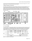
- Kaleido unit, with pre-installed modules and power supplies
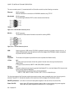
- 2 AC power cords
- Kaleido-RCP (remote control panel)
- RS-422 cable
- DVI-A-to-VGA (HD-15) adapter
- red crossover network cable
- Ethernet jack mounted on a keychain
- CD-ROM of system software, release notes and a Quick Start manual.
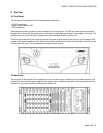
3.2 Rack-mount installation
Kaleido may be installed in a standard 19” rack, using the proper screws and washers ( not included). The Kaleido-
RCP Remote Control Panel may also be installed in a rack using the optional mounting kit (order part #1229-1100-
100).
For proper ventilation, make sure the front and rear panel air vents are not blocked and the air filter is clean.
3.2.1 Installing Kaleido-RCP in a rack using the mounting bracket.
The Kaleido-RCP is designed to be used on a tabletop; however, a mounting kit is available for installation in a
standard 19” equipment rack.
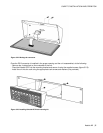
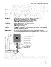
Before attaching the Kaleido-RCP to the mounting kit, you will need to move the RS-422 connector.
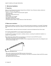
- Remove the 3 screws at the rear of the Kaleido-RCP.
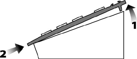
- Slightly lift the rear edge of the cover and push on the front edge toward the back of the unit to dislodge the cover
from the enclosure (figure 3.2.1).
Figure 3.2.1 Removing the cover
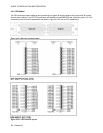
- Remove the 2 screws that hold the DE-9S connector to the enclosure.
- Pry out the metal plate that covers the DE-9 opening on the bottom of the enclosure. Attach the DE-9S connector
into this opening (figure 3.2.2).
- Re-install the cover on the enclosure.