


GUIDE TO INSTALLATION AND OPERATION
10 | Kaleido K2
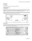
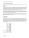
The rear connector panel (11) associated with the Controller module has the following connectors:
Ethernet: RJ-45 connector
Ethernet interface for connection to LAN/WAN networks using TCP-IP.
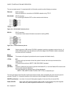
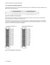
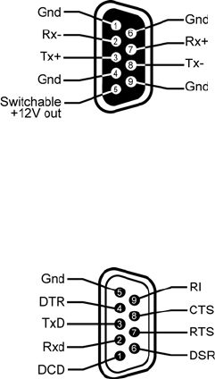
RS-422/485: DE-9S connector
For connecting the Kaleido-RCP or other remote control devices.
Figure 4.4.1.2 RS-422/485 Connector pin-out
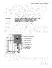
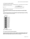
RS-232 : DE-9P connector
To connect to router status information sources for tracking UMDs.
Figure 4.4.1.3 RS-232 Connector pin-out
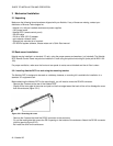
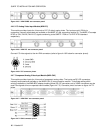
USB: Used to connect a USB mouse, CD-ROM or portable hard disk to upgrade or service the unit. A
similar USB connector may also be found on the front edge of the Controller module, accessible
only when the front is removed.
Mouse,
Keyboard: The mouse and keyboard inputs allow the user to operate the Kaleido locally.
LTC IN: BNC
The time code input connector allows the system’s internal clock to be synchronized to the
station’s time.
LTC signal must conform to SMPTE 12M (EBU-3259-E) standard.
REF IN: BNC
(OPTION) Connect a reference input signal to genlock the Kaleido-K2 (i.e. lock the Kaleido-K2’s internal clock
circuitry to this external reference).
The input reference can conform to any of these standards:
SMPTE 170M, SMPTE 318M, ITU 624-2, BUT 470-6, or composite sync.
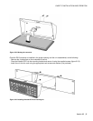
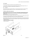
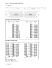
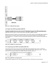
The front card-edge of the Controller module has several controls, some accessible only when the front panel is
removed. Figure 4.4.1.4 shows the location of the controls on the front edge of the Controller module.
ON/OFF pushbutton: turns the unit on and off (the power supplies in the rear of the unit remain ON).
Power ON LED: this bi-color LED reports the general status of the unit and monitors the power supplies.
When off, both power supplies are switched off or not plugged in.