


GUIDE TO INSTALLATION AND OPERATION
Kaleido K2 | 11
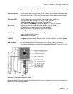
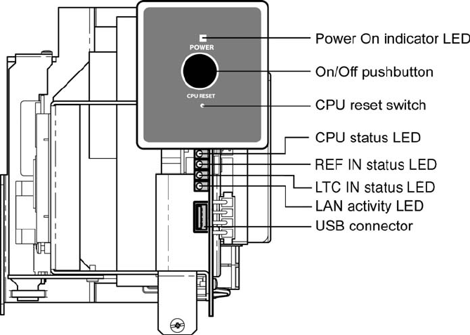
Green indicates that the unit is properly powered and that one or both power supplies are
on.
Red indicates a stand-by mode: the unit is plugged in but the Controller is not switched on.
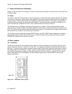
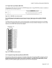
CPU Reset switch: If the Controller is not working properly, it can be reset using this switch without the need
to remove the front panel. Use a paper clip through the hole to depress the reset switch.
CPU status LED: This LED reports the current operational status of the module, as follows:
When turned Off, the Controller is not ready (in boot-up mode).
A blinking yellow / green LED indicates normal operation.
When the LED is not blinking (static yellow or green), an error has occurred.
REF IN LED: Indicates the presence and validity of the Reference (genlock) signal
Off indicates that no valid reference input signal is present
Green indicates that a valid reference input signal is present
Flashing Red indicates a live update is in progress
LTC IN LED: Indicates the presence and validity of the LTC signal.
Green indicates a valid LTC signal.
Red indicates a invalid signal.
LAN LED: turns green to indicate that an Ethernet network has been detected, and flashes yellow
when there is activity on the network.
USB connector: this connector duplicates the functionality of the rear-panel USB port, but is more
conveniently accessible for maintenance purposes when Kaleido-K2 is mounted in a rack.
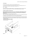
Figure 4.4.1.4 Front edge of Controller module
In the event that the Controller module fails, the Kaleido-K2 will continue to display the incoming video feeds at its
output in the most recent configuration.