


GUIDE TO INSTALLATION AND OPERATION
18 | Kaleido K2
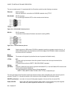
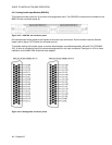
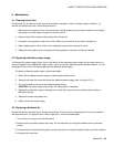
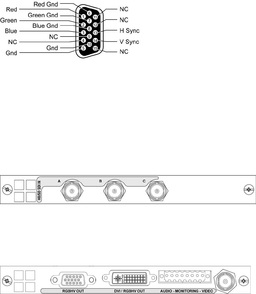
Figure 4.4.8.2 DE-15P connector pinout
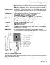
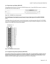
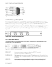
4.4.10 HD-SDI Video Input Module (MWI-HD)
This module provides three standard- and high-definition digital video inputs. The HD/SDI video input module
accepts 4:2:2 standard definition serial digital video signal in either 525 or 625-line format, conform to the SMPTE
259M-C standard and high-definition serial digital video signal conform to the SMPTE-292M-1998 standard.
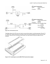
Make sure the input 4:2:2 cable has a maximum length of 100 m (325’), and that all serial digital video connections
are point-to-point. For instance, there must be a point-to-point connection between the 4:2:2 IN BNC and the
source equipment. If a T-connector is used to connect other equipment, the maximum specified cable length is no
longer valid.
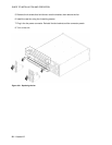
Figure 4.4.10.1 MWI-HD rear connector panel
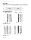
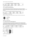
4.4.11 Output Module (MWO-HR)
This module provides all of the outputs from the Kaleido system. Connectors on the associated MWR-HR rear
connector panel (1) are described below.
Figure 4.4.11.1 MWI-HR rear connector panel
RGBVH OUT: Analog progressive scan component video output (DE-15P connector)
Connector pinout is shown on figure 4.4.8.2.
DVI/RGBVH OUT: Digital progressive scan component output (DVI digital connector), with resolution from
800 x 600 to 1600 x 1200 pixels. Note that in 1600 x 1200 the refresh rate is limited to 50
or 59.94 Hz.
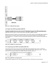
AUDIO OUT: An 8-pin terminal connector is provided to monitor one stereo audio channel, in both
balanced AES3 and analog formats. Refer to figure 4.4.11.2 for connector pinout.