


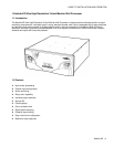
GUIDE TO INSTALLATION AND OPERATION
Kaleido K2 | 3
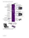
2 Overview
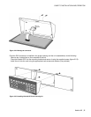
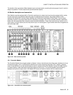
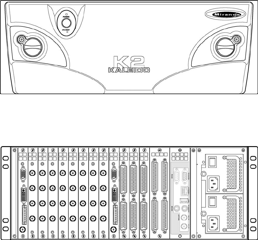
2.1 Front Panel
The front panel of the Kaleido-K2 has three operational elements:
- ON/OFF pushbutton
- System status indicator LED
- CPU reset button.
These items are actually located on the front edge of the controller card. The LED and reset button are accessed
through holes in the panel; the power button on the panel pushes against a smaller button located on the card. The
controller card and the functionality of these controls are described in detail in section 4.4.
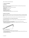
There are also knobs which are turned to open the front panel to give access to the card tray and the status LEDs
located on the cards themselves. Each knob is paired with a screw which must be removed before the knob can be
turned to open the panel. This provides security against casual access.
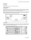
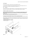
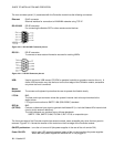
2.2 Rear Panel
The rear panel of the Kaleido-K2 incorporates all of the input and output connectors for the installed modules, and
access to the two redundant power supplies. See section 4.4 for a detailed description of the connectors and their
functionality. The power supplies are described in section 4.2.