


GUIDE TO INSTALLATION AND OPERATION
Kaleido K2 | 9
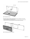
The location of the connectors differs between input and output cards, so placing the wrong type of card in a slot is
simply not possible. The two output cards provide identical outputs.
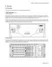
4.4 Module description and connection
Each Kaleido must be equipped with a Controller module and an output card, and may be equipped with a variety
of audio and video input modules depending upon the operational environment. One output module comes
standard with Kaleido-K2, and two output modules are included with the Kaleido-K2 Dual Head. You may add a
secondary module in the single head mode for redundancy purposes. Each of the available modules is described
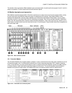
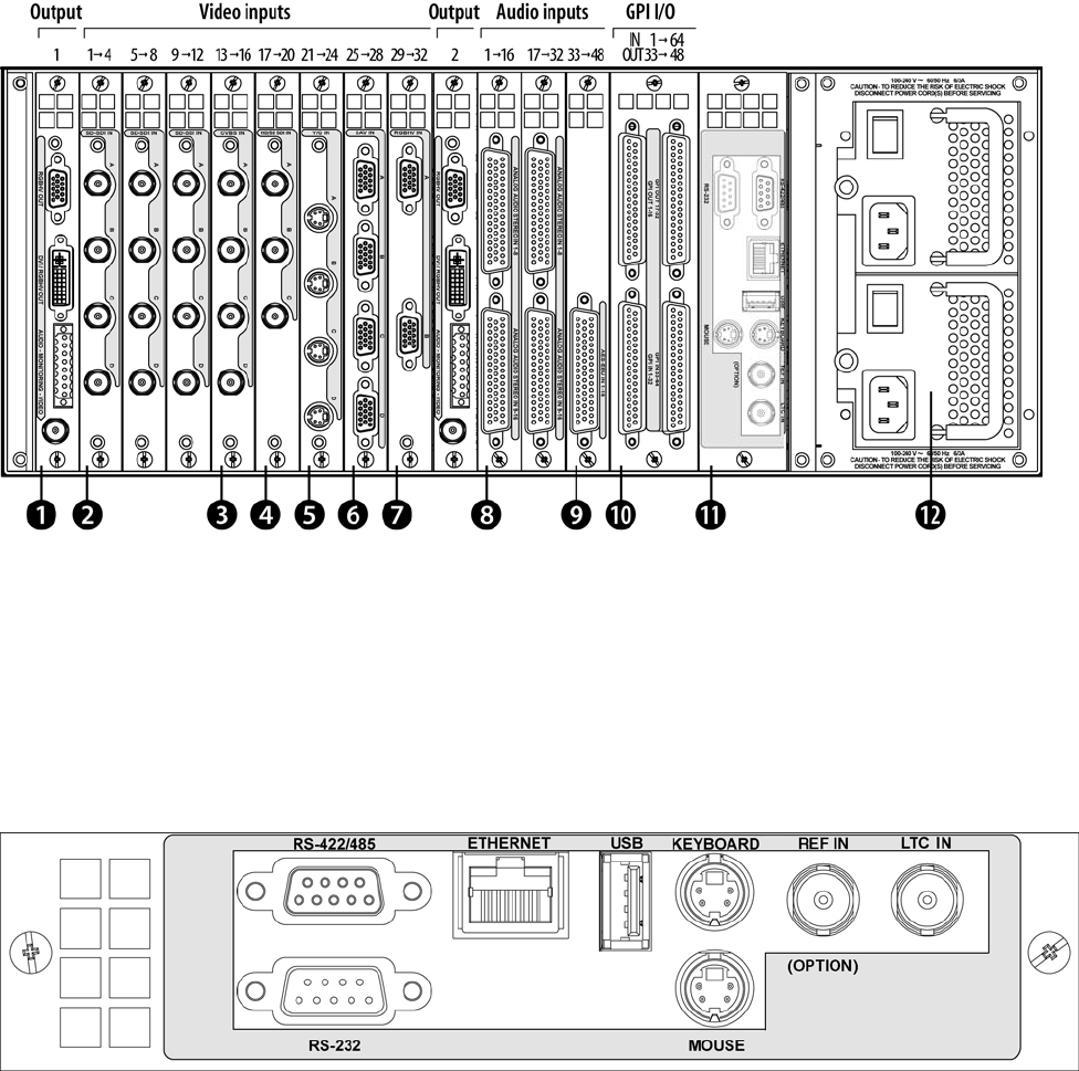
below, as is the associated rear connector panels electrical installation. Each video input slot may receive up to 4
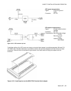
video inputs, and each audio input slot may receive up to 16 audio signals. Figure below shows the arrangement of
the input/output slots.
Figure 4.4.1 Rear connector panels
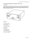
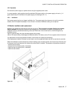
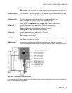
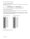
4.4.1 Controller Module
The Controller Module is the largest module in Kaleido. It sits on the left-hand side of the frame, beside and in front
of the power supply units. It incorporates the Kaleido’s on-board computing resources (CPU, memory, graphics
card), a hard disk drive, and the communication ports for remote control of the Kaleido. Some of the data used for
on-screen display is also received through these communication ports. This module handles communications
between the input and output cards in the Kaleido-K2 frame, and communications with the outside world.
Figure 4.4.1.1 Controller rear connector panel