


MITSUBISHI ELECTRIC MOTHERBOARD DIVISION PAGE 13 OF 45
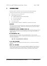
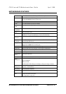
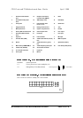
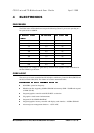
1 Chasis Intrusion Header
PL17
15 Graphics and memory
controller hub (GMCH)
C RJ45
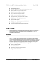
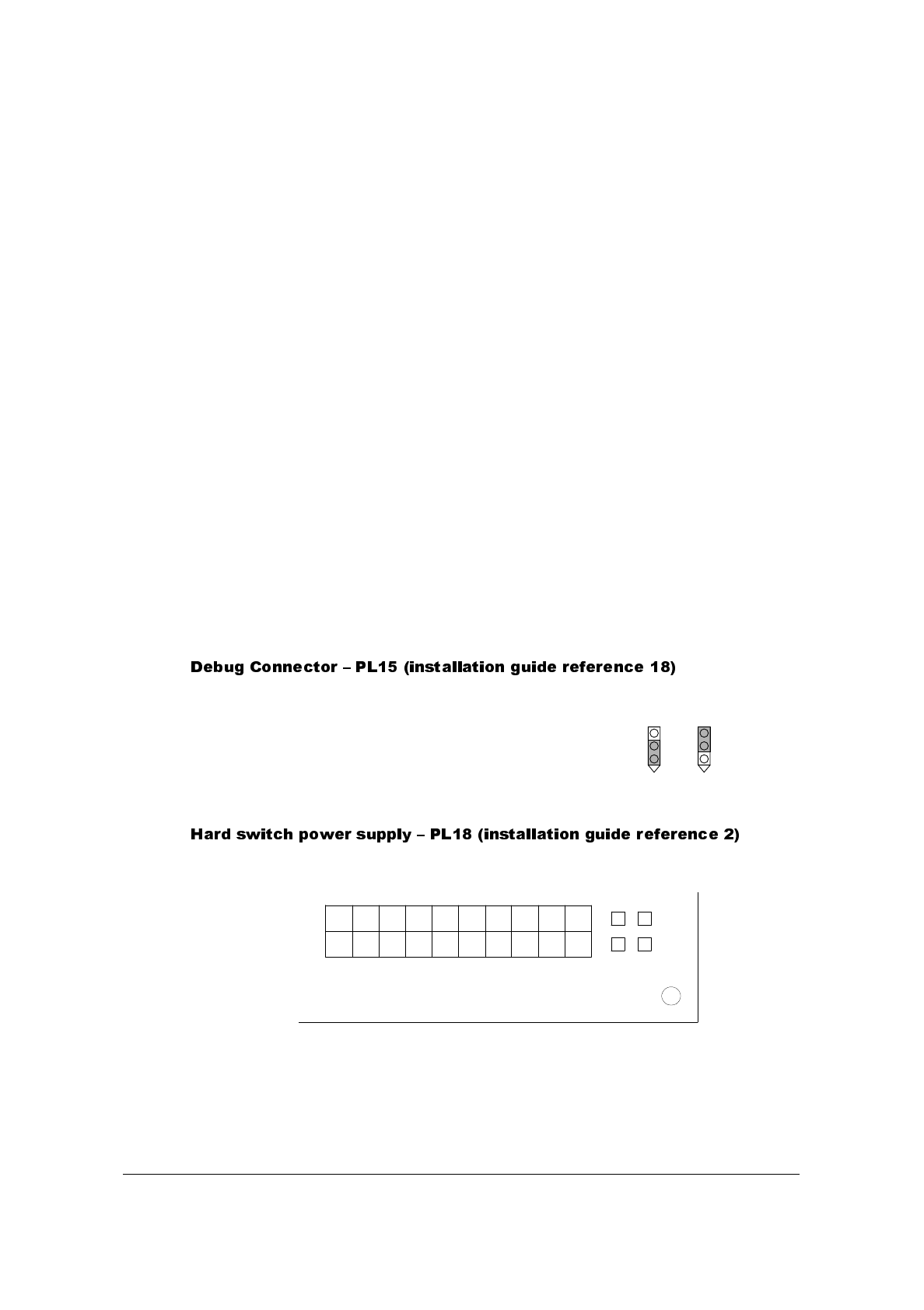
2 Hard Switch PSU jumper
PL18
16 4MB display cache D USB (Dual)
3 Front panel 17 PCI expansion slots
PL10,11,12,13
E Serial Port 1
4 Floppy disk PL21 18 Debug connector PL15 F VGA
5 Main power PL19 19 System fan power PL9 G Parallel
6 Primary IDE Controller PL22 20 CPU fan power PL8 H Line output
7 Secondary IDE Controller
PL16
21 Processor I Line input
8 Super I/O 22 LAN controller J Mic input
9 Firmware Hub (FWH) 23 ATAPI audio LINE in (natural)
PL5
K MIDI & Joystick
10 Buzzer 24 ATAPI CD audio in (green)
PL6
L Speed LED (Yellow)
11
12
13
14
Main memory DIMMs MM1,2
Lithium Cell (CR2032)
I/O controller hub (ICH)
Clock synth
25
26
A
B
ATAPI telephony (black) PL7
AC’97 Audio controller
Keyboard
Mouse
M Link/Activity LED (Green)
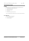
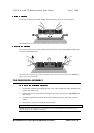
Not fitted Normal operation
1-2 Forces processor to lowest multiplier (x2)
2-3
Debug Mode (To be Determined)
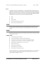
Link 1-2 and 3-4 when 5V standby rail is not available
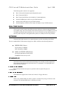
Clear CMOSNormal Operation
PL19
PL18
1
3
2
4