


MITSUBISHI ELECTRIC MOTHERBOARD DIVISION PAGE 18 OF 45
PCI Bus – supports Rev 2.2 spec and 4/ 6 (optional) master devices
Dual UltraDMA33/ 66 (optional) IDE controller
Dual USB controller (12Mbps or 1.5Mbps)
AC’97 link for audio/ telephony CODEC’s
SMbus controller (motherboard management)
Interrupt Controller – integrated I/O APIC capability
GPIO functions – TTL, Open-Drain, Inversion
Enhanced DMA controller
Real-time clock – 256 byte battery-backed CMOS RAM
ACPI power management logic
Low Pin Count (LPC) interface (Super I/O connection)
The second level cache is contained within the processor module. There is no provision for a
third level cache. Cache size is determined by the type of CPU fitted, refer to your CPU
manufacturer for this information.
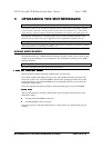
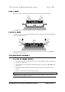
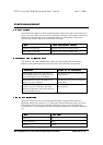
There are two DIMM sockets on the motherboards that accept 168-pin un-buffered SDRAM
modules to the Intel PC SDRAM un-buffered memory module specification. PC100 modules are
required. All modules must support SPD (serial presence detect) to allow the BIOS to determine
the memory configuration and set up the chipset optimally. These modules contain a small
EEPROM that describes the module capabilities in detail - including speed, capacity and
organisation. EDO and registered DIMM modules are not supported.
64-bit or 72-bit ECC modules.
2 or 4 bank organisation
Asymmetric or symmetric memory addressing.
Single or double-sided modules.