


MITSUBISHI ELECTRIC MOTHERBOARD DIVISION PAGE 19 OF 45
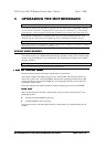
The BIOS is contained in a flash ROM device – Firmware Hub (FWH) soldered directly to the
motherboard and includes the code listed below. The motherboard will automatically perform a
BIOS recovery operation if it detects a valid recovery disk during the boot sequence. The BIOS
ROM is accessed as a single linear region in the memory space from 4GB-128kB (0FFFE0000 -
0FFFFFFFFh) and copied at the top of ISA memory (0E0000 - 0FFFFFh).
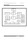
USB
DMI
Setup-in-ROM
Intel microcode update support and code
Power and system management code
The FC810 microATX motherboard contains an integrated graphics controller. However an
alternative adapter can be used and fitted to one of the expansion slots. This may be a PCI
product.
The audio system is based around an AC’97 compliant controller. When not fitted, the standard
PC beep function remains.
AC-link digital interface with ICH
16-bit stereo full-duplex codec with fixed 48K sampling rate
3 analog line-level stereo inputs for connection from LINE IN, CD, AUX
2 analog line-level mono inputs for connection from PHONE, PC BEEP
Mono MIC input switchable form two external sources
Stereo line level output
Mono output for speakerphone
Programmable power management
Tone, loudness, 3D stereo enhancements
One power amplifier is used - a National Semiconductor LM4881 ’Boomer’ to drive the LINE-
out jack socket and the optional internal speaker. The microphone input provides power to
enable condenser microphones to be used.