


EN-7
ENGLISH
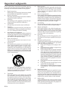
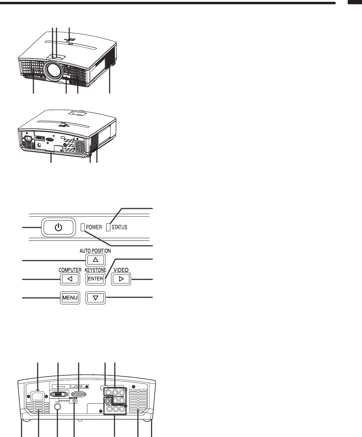
Overview
321
57
1098
64
2
1
3
4
8
5
6
7
9
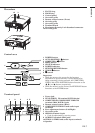
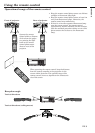
1 FOCUS ring
2 ZOOM ring
3 Control panel
4 Air outlet grille
5 Remote control sensor (Front)
6 Air inlet grille
7 Air outlet grille
8 Terminal board
9 Kensington Security Lock Standard connector
10 Air inlet grille
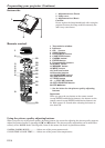
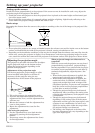
Control area
1 POWER button
2 AUTO POSITION /
{{
{{
{ button
3 COMPUTER /
$$
$$
$ button
4 MENU button
5 STATUS indicator
6 POWER indicator
7 KEYSTONE/ENTER button
8 VIDEO/
%%
%%
% button
9
}}
}}
} button
Important:
• While the menu or the screen for the keystone
adjustment or password entry is being displayed or
image capturing is being executed, the COMPUTER,
VIDEO, and AUTO POSITION buttons function as the
$, %, and { buttons respectively.
• While the menu is on the screen, the KEYSTONE button
functions as the ENTER button.
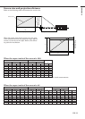
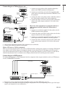
COMPONENT VIDEO IN
1 2 3 4 5
876 691011
Terminal panel
1 Power jack
2 DVI-D (HDCP) IN terminal (DVI-D 24-pin)
3 COMPUTER IN/ COMPONENT VIDEO IN
terminal (Mini D-SUB 15-pin)
4 Remote control sensor (Rear)
5 COMPONENT VIDEO IN and audio input
terminals
6 Foot adjustment buttons (Left/Right)
7 Air outlet grille
8 SERIAL terminal (8-pin)
• Used for adjustment by service person.
9 AUDIO IN terminal (Mini jack)
10 VIDEO / S-VIDEO and audio input terminals
11 Speaker