


MITSUBISHI ELECTRIC 9800A SERIES UPS
MITSUBISHI
ELECTRIC
9800A SERIES UPS
OWNERS / TECHNICAL MANUAL
Page Number:
1-5
1.3 Overview
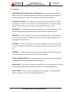
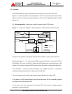
The UPS provides two power paths between the utility source and the critical load.
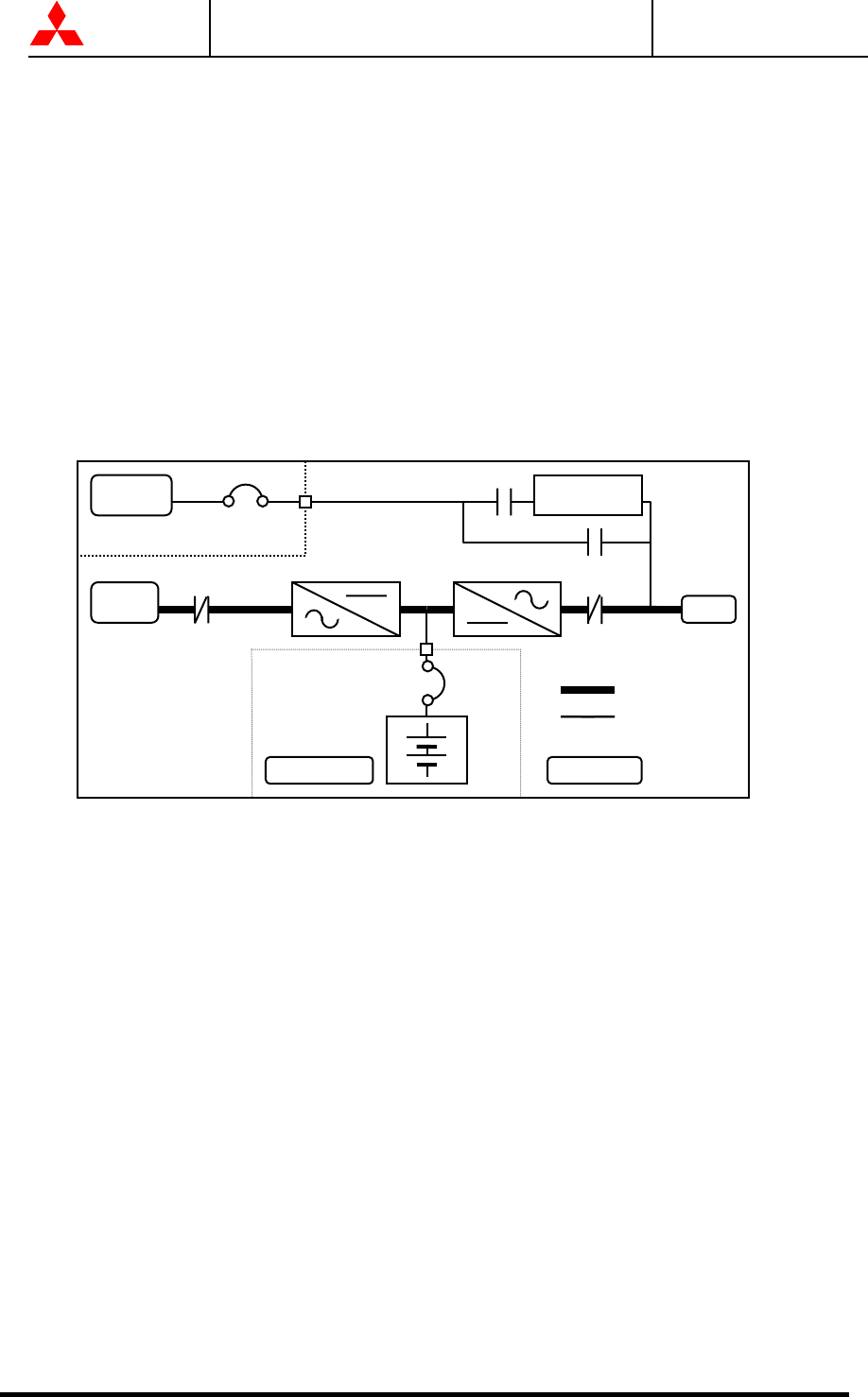
Figure 1.1 shows the path for normal operation, with the load powered from the inverter.
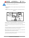
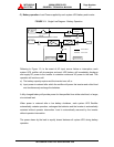
Figure 1.2 shows the path for bypass operation, with the load supplied through the static
bypass line.
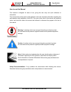
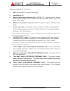
A) Normal operation: Load power supplied by each system UPS inverter.
Figure 1.1 Single Line Diagram - Normal Operation: Load powered by UPS inverters
During normal operation, the path through the UPS inverters is used to power the load.
Referring to Figure 1.1: For each system UPS, the Input AC power is converted to DC by
the Rectifier. DC power is utilized to charge the UPS battery and to provide power to the
Inverter. The Inverter converts the DC power to clean AC power to supply the critical load.
The conversion - inversion process eliminates any voltage transients or fluctuations
existing in the input power before it reaches the critical load.
The power drawn by the critical load is equally shared between all system UPS.
In the event of a UPS module failure, the critical load power will be continually supplied
and shared by all other system UPS.
In the event of a load overcurrent, all system UPS will transfer to bypass without
interruption to the critical load.
CB1
Static Transfer
Switch
AC Bypass
In
p
ut
AC input
CB
CB3
52S
52C
User supplied
MCCB
UPS ModuleBattery cabinet
CB2
Power Flow
Not in Use
RECTIFIER INVERTER
Output