


MITSUBISHI ELECTRIC 9800A SERIES UPS
MITSUBISHI
ELECTRIC
9800A SERIES UPS
OWNERS / TECHNICAL MANUAL
Page Number:
3-3
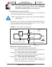
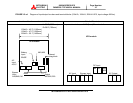
b.) DC Input to UPS
1. Positive cable to BP bus bar in UPS rectifier section.
2. Negative cable to BN bus bar in UPS rectifier section.
3. Connect the grounding conductor from the input service entrance to the UPS ground
bar.
4. Two (2) sources feeding the UPS:
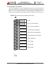
(1) Connect the rectifier input power cables from the input service entrance to the
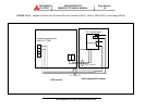
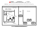
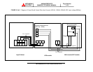
rectifier input power terminals, identified as A, B, C in Figures 3.2-a~g. Input
cables must be sized for an ampere rating larger than the maximum input drawn
by the rectifier. (Refer to equipment nameplate for current ratings.) Confirm that
an external bypass input circuit breaker (MCCB) is installed (refer to WARNING 2,
page 1-2). Connect the bypass input power cables from the input service entrance
to the bypass input power terminals, identified as A40, B40, C40 and N40 in
Figures 3.2-a~g. Bypass input cables must be sized for an ampere rating larger
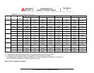
than the maximum output current capacity of the UPS. Refer to Table 3.4 for
recommended cable sizes.
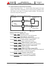
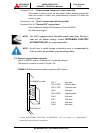
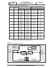
(2) Connect the external signal terminal block as desired. Refer to section 2.4 and
Figure 2.15 for functional description. 2mm
2
, or less, shielded conductor is
recommended.
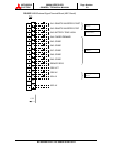
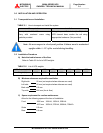
5. One (1) source feeding the UPS:
(1) Confirm that an external input circuit breaker sized to protect both the rectifier
input and the bypass line is installed. (Refer to equipment nameplate for current
ratings.) Connect the bypass input power cables from the input service entrance
to the bypass input power terminals, identified as A40, B40, C40 and N40 in
Figures 3.2-a~g Input cables must be sized for an ampere rating larger than the
maximum current capacity of the UPS. Refer to Table 3.4 for recommended cable
sizes.
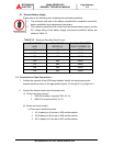
(2) Using adequately sized conductors and referring to the appropriate figure
identified in Figures 3.2-a~g, connect jumper bypass terminals A40, B40, C40 to
rectifier input power terminals A, B, C as identified in Figures 3.2-a~g.