


MITSUBISHI ELECTRIC 9800A SERIES UPS
MITSUBISHI
ELECTRIC
9800A SERIES UPS
OWNERS / TECHNICAL MANUAL
Page Number:
2-3
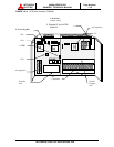
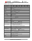
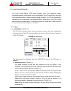
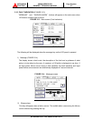
2.3 Liquid Crystal Display (8)
The Liquid Crystal Display (LCD) panel indicates power flow, measured values,
operational guidance, data records and error messages. The LCD panel has a back-light
which facilitates viewing in different ambient lighting conditions. The LCD will automatically
clear and turn off, if the screen is not activated within 3 minute period. The LCD is turned
back on when it is touched again. The ERROR indicator is cleared after 24 hours and can
be reproduced by pressing any key on the panel.
2.3.1 Menu
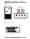
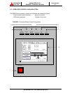
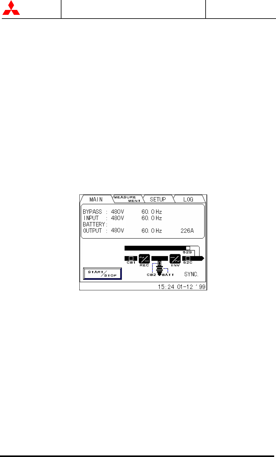
A) MAIN MENU (FIGURE 2.2)
The LCD panel indicates power flow and measured values, while also operating the
start/stop function. The LCD panel also allows the user to verify the status and operation
of the UPS Module.
FIGURE 2.2 Main screen
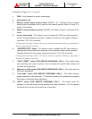
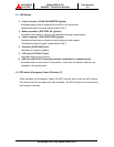
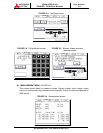
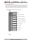
The following will be displayed when the START/STOP key on the LCD panel is
pressed:
1) Start/Stop screen (FIGURE 2.3)
The display indicates the start and stop operations for the UPS system. If this
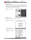
operation is PIN protected, the user is required to enter the security PIN before the
screen can be accessed. Refer to (FIGURE 2.4).
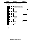
When in remote mode, the message “REMOTE operating model” will appear on this
Screen. The user cannot operate the start and stop functions without changing the
setup from remote mode to local mode.
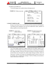
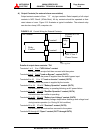
When bypass voltage is abnormal, the message “Bypass voltage abnormal” will appear.
-Start: When the bypass voltage is abnormal, the LCD asks the operator if an
interrupted transfer is acceptable (Load may be lost). (FIGURE 2.5)
-Stop: When the bypass voltage is abnormal, the user cannot transfer from inverter
to bypass line.
540V