


MITSUBISHI ELECTRIC 9800A SERIES UPS
MITSUBISHI
ELECTRIC
9800A SERIES UPS
OWNERS / TECHNICAL MANUAL
Page Number:
3-4
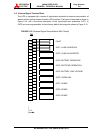
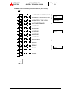
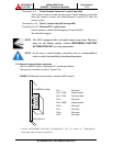
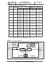
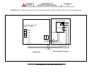
(3) Connect the external signal terminal block as desired. Refer to section 2.4 and
Figure 2.15 for functional description. 2mm
2
, or less, shielded conductor is
recommended.
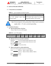
NOTES:
1. Confirm that all UPS internal contactors (breakers) "CB1", "CB2", and
"CB3" are open before energizing UPS.
2. UPS power terminals are supplied with stud type fittings. It is recommended
that compression lugs be used to fasten all input/output power cables.
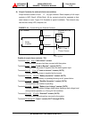
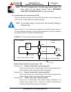
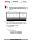
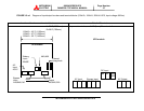
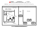
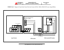
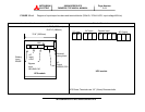
6. Procedure for Cable Connections for Parallel System
(1) Confirm the number of units to be connected in parallel. Identify the input/output
power terminal blocks and control wire connections for parallel systems as shown
in the appropriate Figures 3.4a~c.
(2) Connect the external control wire and power wire.
a.) Control wire connection
Parallel configuration Wiring (Refer to Figure 3.4a~c )
- Critical Load Cabinet (CLC) TB1 to UPSn IOAU-04,TN2.
- Parallel Control CN92, CN93, In, Out cables between UPS modules
b.) Power wire connection
From UPS AC Output Terminals to CLC (Refer to Figure 3.4a~c)