


MITSUBISHI ELECTRIC 9800A SERIES UPS
MITSUBISHI
ELECTRIC
9800A SERIES UPS
OWNERS / TECHNICAL MANUAL
Page Number:
iv
List of Figures
Figure 1.1 Single Line Diagram-Normal Operation.................................................... 1-5
Figure 1.2 Single Line Diagram-Bypass Operation ................................................... 1-6
Figure 1.3 Single Line Diagram-Battery Operation.................................................... 1-7
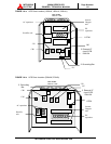
Figure 1.4 UPS Parts Location................................................................................... 1-8
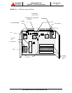
Figure 1.5 UPS Parts Location (Continued) .............................................................. 1-11
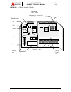
Figure 1.6 External I/F circuit PCB IOAU-04 ............................................................ 1-11
Figure 2.1 Operation/Display Panel........................................................................... 2-1
Figure 2.2 Main Screen.............................................................................................. 2-3
Figure 2.3 Start/Stop Screen...................................................................................... 2-4
Figure 2.4 PIN Protection Screen .............................................................................. 2-4
Figure 2.5 Bypass Voltage Abnormal Message Screen............................................ 2-4
Figure 2.6 Measurement Screen................................................................................ 2-4
Figure 2.7 Setup Screen ............................................................................................ 2-5
Figure 2.8 Log Select Screen..................................................................................... 2-5
Figure 2.9 Event Log Screen ..................................................................................... 2-5
Figure 2.10 Battery Log Screen ................................................................................. 2-6
Figure 2.11 Main Screen (Battery Operation) ............................................................ 2-6
Figure 2.12 Measurement Screen (Battery Operation) ............................................... 2-6
Figure 2.13 Main Screen (Fault Indication) ................................................................ 2-7
Figure 2.14 Message Screen ..................................................................................... 2-7
Figure 2.15 External Signal Terminal Block................................................................. 2-8
Figure 2.16 Control Wiring for External Contacts ........................................................ 2-10
Figure 2.17 Remote "Start" Contact Connections ....................................................... 2-11
Figure 2.18 External communication connector .......................................................... 2-12
Figure 3.1 UPS Terminal Designation ...................................................................... 3-6
Figure 3.2 Diagram of input/output bus bars and terminal blocks ........................... 3-7
Figure 3.3 Diagram of Rectifier Cabinet & Inverter Cabinet Inter-connect .............. 3-19
Figure 3.4 Diagram of Power and Control Wire Connect (Parallel Connection) ....... 3-21
Figure 3.5 Operation Procedures: Start Up/Shut Down Procedure........................... 3-24