


MITSUBISHI ELECTRIC 9800A SERIES UPS
MITSUBISHI
ELECTRIC
9800A SERIES UPS
OWNERS / TECHNICAL MANUAL
Page Number:
2-12
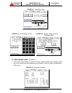
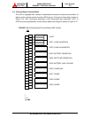
Terminals 7 to 8 "Power Demand Command" contact input (IN4)
This contact is used to control the input power. Power demand is turned ON
when the contact is closed, and power demand is turned OFF when the
contact is open.
Terminals 9 to 18 "Spare" contact input (IN5 through IN9)
Terminals 19 to 20 "Remote EPO" contact input
Used to perform a remote UPS Emergency Power Off (EPO).
The load will be dropped.
NOTE:
The UPS is equipped with a selectable output contact item. The above
items are the default settings. Contact MITSUBISHI ELECTRIC
AUTOMATION, INC. for setup information.
NOTE :
In all cases, a switch having a protective cover is recommended in
order to reduce the possibility of accidental operation.
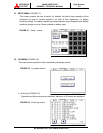
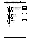
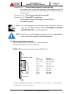
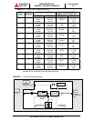
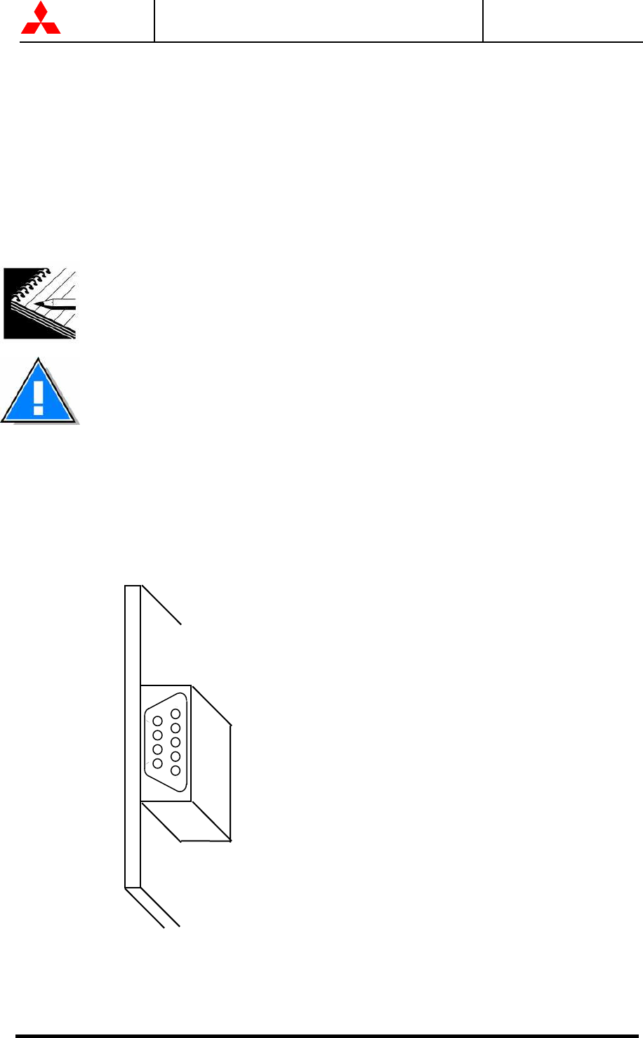
2.5 External communication connector
This is an RS232C port for “DiamondLink”* monitoring software.
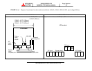
The layout of connector is shown in Figure 2.18.
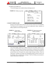
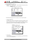
FIGURE 2.18 External communication connector (NEC Class2)
Pin 1. : Not used
Pin 2. RXD : Receive data
Pin 3. TXD : Transmit data
Pin 4. : Not used
Pin 5. GND : Signal ground
Pin 6. : Not used
Pin 7. : Not used
Pin 8. : Not used
Pin 9. : Not used
* Consult MITSUBISHI ELECTRIC AUTOMATION, INC. for details on
“
DiamondLink
”
monitoring software and its capabilities.
D-SUB 9Pin (male)
PCB IOAU-04
1
2
3
4
5
6
7
8
9