


MITSUBISHI ELECTRIC 9800A SERIES UPS
MITSUBISHI
ELECTRIC
9800A SERIES UPS
OWNERS / TECHNICAL MANUAL
Page Number:
3-2
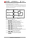
D) External Battery Supply
Please refer to the following when installing and maintaining batteries:
1. The customer shall refer to the battery manufacturer's installation manual for
battery installation and maintenance instructions.
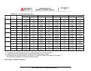
2. The maximum permitted fault current from the remote battery supply, and the
DC voltage rating of the battery supply over-current protective device are
shown in Table 3.3.
TABLE 3.3 Maximum Permitted Fault Current
UPS CAPACITY
(kVA)
DC VOLTAGE
RATING (V)
MAXIMUM PERMITTED
FAULT CURRENT (A)
100 480 25000
150 480 25000
225 480 25000
300 480 25000
375 480 25000
500 480 25000
750 480 25000
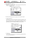
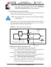
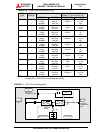
3.3 Procedure for Cable Connections *
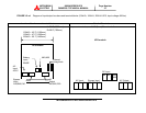
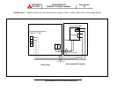
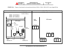
1. Confirm the capacity of the UPS being installed. Identify the input/output power
terminal blocks as shown in the appropriate Figures 3.1 through 3.2-a~g,Figure 3.3.
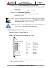
2. Connect the internal control wire and power wire.
(1) Control wire Inter-connect
1. CB2 NO Auxiliary to terminal TN2- 23, 24.
2. CB2-UVT to terminal TN2- 21, 22.
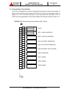
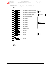
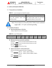
(2) Power wire Inter-connect
a.) From user’s distribution panel
1. X1 (A-phase) to A bus bar in UPS rectifier section.
2. X2 (B-phase) to B bus bar in UPS rectifier section.
3. X3 (C-phase) to C bus bar in UPS rectifier section.