


CiM-550 IP Enabled Satellite Modem Rev. 2
Installation CD/CIM550.IOM
14
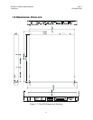
The CiM-550 is very light - under 7 lbs (3.2 kgs), and very short - 12 ins (305 mm). For
this reason, it has not been designed to have rack slides mounted to the side of the
chassis. However, Comtech EF Data recommends that some method of support within the
rack should be employed, such as rack shelves. If there is any doubt, please consult the
factory.
2.3 CONFIGURATION
There are no internal jumpers to configure, no interface cards to install, and no other
options to install. All configuration is carried out entirely in software. The unit should
first be configured locally, using the front panel keypad and display. The unit will ship
with a default 64 kbps, QPSK, Rate 1/2 configuration. Please refer to the ‘FRONT
PANEL OPERATION’ section for details on how to fully configure the unit for the
desired operating parameters.
2.4 SELECT INTERNAL IF LOOP
Correct operation of the unit may be verified rapidly, without the need for externally
connected equipment. From the top level menu, select TEST, then IF LOOP (refer to the
‘FRONT PANEL OPERATION’ section) The demod should synchronize, and the green
RECEIVE TRAFFIC LED should illuminate. If the unit does not pass this test, call the
factory for assistance.
2.5 CONNECT EXTERNAL CABLES
Having verified correct operation in IF loop, enter the desired configuration, and proceed
to connect all external cables. If difficulties occur, please call the factory for assistance.
Please note that the modulator gives an output power level in the range 0 to -20 dBm, and
the demodulator expects to see a signal in the range -30 to -60 dBm.
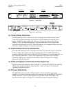
2.6 CONNECTOR DESCRIPTION
External cables are attached to connectors on the rear panel of the CiM-550. These
comprise the IEC line input connector, the Receive and Transmit IF connectors, the Data
connector, Alarms connector, Remote Control connector, and Auxiliary Serial connector.
See Appendix K for detailed connector pinouts.
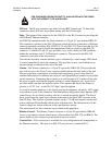
The IEC line input connector contains the ON/OFF switch for the unit. It is also fitted
with two fuses - one each for line and neutral connections (or L1, L2, where appropriate).
These are contained within the body of the connector, behind a small plastic flap.
For 230 volt AC operation, use T0.5A, (slow-blow) 20 mm fuses.
For 115 volt AC operation, use T1A fuses, (slow-blow) 20 mm fuses.