


SLM-5650 Satellite Modem Revision 1
Maintenance MN/SLM5650.IOM
5–9
5.3 Fault Isolation
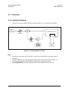
The design of the modem allows for removal and replacement of some faulty components in
the field. The optional interface PCB’s can be removed from the modem through the rear
panel, without requiring special tools. The TURBO PCB and power supply can be replaced if
the top cover is removed.
CAUTION
This equipment contains parts and assemblies sensitive to damage by ESD.
Use ESD precautionary procedures when touching, removing, or inserting
PCBs.
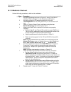
The fault monitoring capability of the modem assists the operator in determining which PCB
has failed. If possible, replace the faulty PCB and return the damaged board to the Comtech
EF Data Customer Support Department for repair. If not return the complete modem.
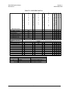
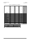
The fault isolation procedure lists the following categories of faults or alarms.
• Modulator
• Demodulator
• Transmit Interface
• Receive Interface
• Unit (Common Equipment)
Notes:
1. Each fault or alarm category includes possible problems and the appropriate
action required to repair the modem.
2. If any of the troubleshooting procedures mentioned earlier in this chapter do not
isolate the problem, and Comtech EF Data Customer Support assistance is necessary,
have the following information available for the representative:
• Modem configuration. Modem configuration includes the modulator,
demodulator, interface, or local AUPC sections.
• Faults (active or stored).
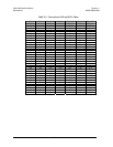
5.4 System Faults/Alarms