


SLM-5650 Satellite Modem Revision 2
Installation MN/SLM5650.IOM
2–4
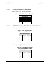
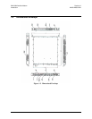
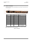
2.3 External Connections
The connectors on the rear panel of the SLM-5650 are shown in Figure 2-4 and described in the
following paragraphs.
Name
Ref Des
Connector Type
Function
EXT REF J1 TNC Modem Reference
Tx J11 TNC 70/140 MHz
Rx J3 TNC 70/140 MHz
Tx J2 Type N L-Band
Rx J4 Type N L-Band
Ethernet J5 RJ-45 10/100 Base-T, Remote Control
EIA-530 J6 25-Pin Female Data Input /Output, to 20 Mbps
HSSI J7 52-Pin Female Data Input /Output, to 52 Mbps
Overhead Data P1 25-Pin Male Not Used
Alarms J8 9-Pin Female Form-C Alarms
Auxiliary J9 15-Pin Female
Remote J10 9-Pin Female Remote Interface
AC IEC Modem Power
Ground 10-32 stud Chassis Grounding
Interface Option
Slot
Supports optional data
interfaces, including but not
limited to the Gigabit Ethernet
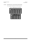
Note: To maintain compliance with the European EMC Directive (EN55022, EN50082-1)
properly shielded cables are required for all data I/O.
Figure 2-3. Rear Panel