


UC-7420/7410 User’s Manual Introduction
1-9
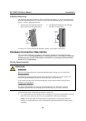
DIN-Rail Mounting
The aluminum DIN-Rail attachment plate is included in the package. If you need to reattach the
DIN-Rail attachment plate to UC-7420/7410, make sure the stiff metal spring is situated towards
the top, as shown in the figures below.
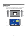
1. Insert the top of the DIN-Rail into the
slot just below the stiff metal spring.
2. The DIN-Rail attachment unit will snap
into place as shown below.
metal
spring
DIN-Rail
metal
spring
DIN-Rail
To remove UC-7420/7410 from the DIN-Rail, simply reverse Steps 1 and 2 above.
Hardware Connection Description
This section describes how to connect UC-7420/7410 to serial devices for first time testing
purposes. We cover Wiring Requirements, Connecting the Power, Grounding UC-7420/7410,
Connecting to the Network, Connecting to a Serial Device, Connecting to the Console Port,
PCMCIA, and CompactFlash.
Wiring Requirements
ATTENTION
Safety First!
Be sure to disconnect the power cord before installing and/or wiring your UC-7420/7410.
Wiring Caution!
Calculate the maximum possible current in each power wire and common wire. Observe all
electrical codes dictating the maximum current allowable for each wire size.
If the current goes above the maximum ratings, the wiring could overheat, causing serious
damage to your equipment.
Temperature Caution!
Be careful when handling UC-7420/7410. When plugged in, UC-7420/7410’s internal
components generate heat, and consequently the outer casing may feel hot to the touch.
You should also observe the following common wiring rules:
y Use separate paths to route wiring for power and devices. If power wiring and device wiring
paths must cross, make sure the wires are perpendicular at the intersection point.
NOTE: Do not run signal or communication wiring and power wiring in the same wire
conduit. To avoid interference, wires with different signal characteristics should be routed
separately.