


CX-MB-EVA2 User's Manual Hardware
25
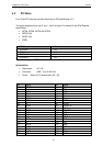
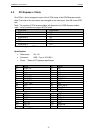
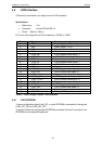
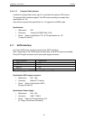
4.6 LVDS-Interface
LCDs can be connected via a single channel LVDS interface:
Specification:
References: X14
Connector: Hirose DF19G-20P-1H
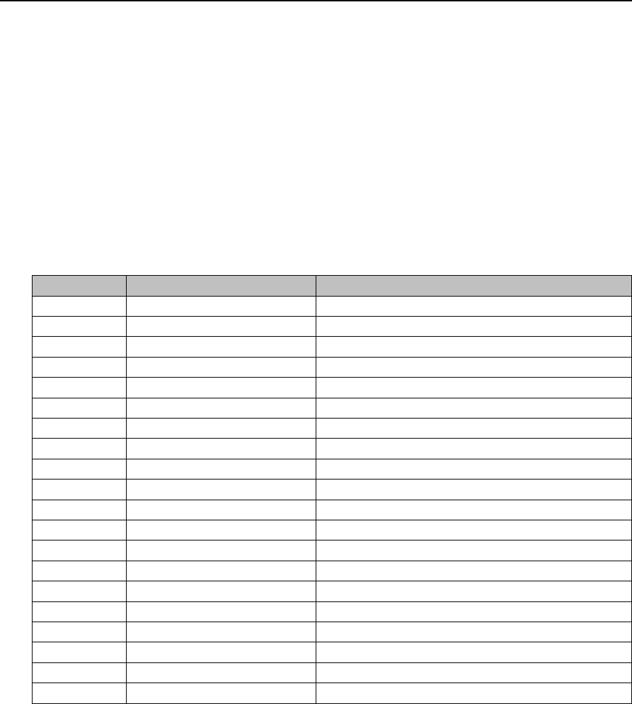
Pinout: Refer to Table 4
Pin 20 can be configured via 0 Ohm resistors to “OPEN” or “GND”
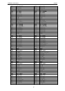
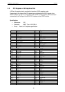
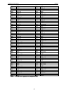
Pin Signal name Function
1 VDD Power Supply: +3.3V
2 VDD Power Supply: +3.3V
3 VSS Ground
4 VSS Ground
5 LVDS_A0- LVDS Negative data signal (-)
6 LVDS_A0+ LVDS Positive data signal (+)
7 VSS Ground
8 LVDS_A1- LVDS Negative data signal (-)
9 LVDS_A1+ LVDS Positive data signal (+)
10 VSS Ground
11 LVDS_A2- LVDS Negative data signal (-)
12 LVDS_A2+ LVDS Positive data signal (+)
13 VSS Ground
14 LVDS_A_CK- LVDS Negative clock signal (-)
15 LVDS_A_CK+ LVDS Positive clock signal (+)
16 VSS Ground
17 LVDS_A3- LVDS Negative data signal (-)
18 LVDS_A3+ LVDS Positive data signal (+)
19 VSS Ground
20 NC / VSS Reserved / Ground
Table 9 Pinout Single Channel LVDS-Interface
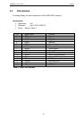
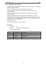
4.6.1 LVDS EEPROM
To store configuration data of the LCD, a serial EEPROM is connected to the signals
LVDS_I2C_CK and LVDS_I2C_DAT.
To avoid conflicts with configuration EEPROMs connected via the JILI connector, this
EEPROM can be assembled optionally.