


CX-MB-EVA2 User's Manual
6
Tables
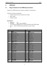
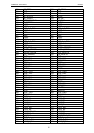
Table 1 COMExpress Connector Rows A and B ............................................................16
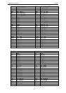
Table 2 COMExpress Connector Rows C and D ............................................................18
Table 3 Assignment PCI slot to connector reference ....................................................19
Table 4 Pin out PCI ...........................................................................................................20
Table 5 Assignment PCIe Lane to connector reference ................................................21
Table 6 Pin out PCI Express ............................................................................................21
Table 6 Pin out PCI Express x16 Graphics Slot .............................................................23
Table 5 Pinout VGA Interface ..........................................................................................24
Table 6 Pinout Single Channel LVDS-Interface ..............................................................25
Table 7 Pinout Backlight ..................................................................................................26
Table 8 Pinout TV-Out ......................................................................................................28
Table 9 Pinout TV-Out Pin header ...................................................................................28
Table 10 Pinout Microphone ............................................................................................29
Table 11 Pinout LineIn .....................................................................................................30
Table 12 Pinout LineOut ..................................................................................................30
Table 13 Pinout Headphone .............................................................................................30
Table 14 Pinout LineOut ..................................................................................................31
Table 15 Assignment SATA Channel to Connector Reference .....................................32
Table 16 Assignment USB Ports .....................................................................................33
Table 17 Pinout LPC-Slot .................................................................................................34
Table 18 Pinout I/O-Connector ........................................................................................35
Table 19 Pinout GPIO connector .....................................................................................36
Table 20 Pinout COM Ports ..............................................................................................37
Table 21 Pinout IrDA ........................................................................................................38
Table 22 Pinout Upper PS/2 Jack ....................................................................................38
Table 23 Pinout Lower PS/2 Jack ....................................................................................38
Table 24 Pinout Fan Interface ..........................................................................................39
Table 25 Pinout Fan Interface ..........................................................................................39
Table 26 Pinout POST Display (HP-POD) ........................................................................41
Table 27 Pinout Lattice Programming Interface .............................................................42