


CX-MB-EVA2 User's Manual Hardware
36
4.16 GPIO
The COM Express module provides four general purpose outputs and four general
purpose inputs.
The GPIs have PullUp resistors and are routed to a dip switch (SW1103). With the dip
switch the GPIs can be connected to ground. The assignment GPI – switch – level is
printed on the PCB.
If the PullUp resistors are not populated, you can switch LPC_SMI# or HWM_SMI# to
GPI0, GPI1, GPI2 or GPI3 with jumper JP1101.
The GPOs are connected to LEDs for optically status display.
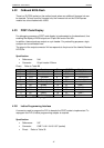
Specification:
References: X35
Connector: CAB 1002-161-036
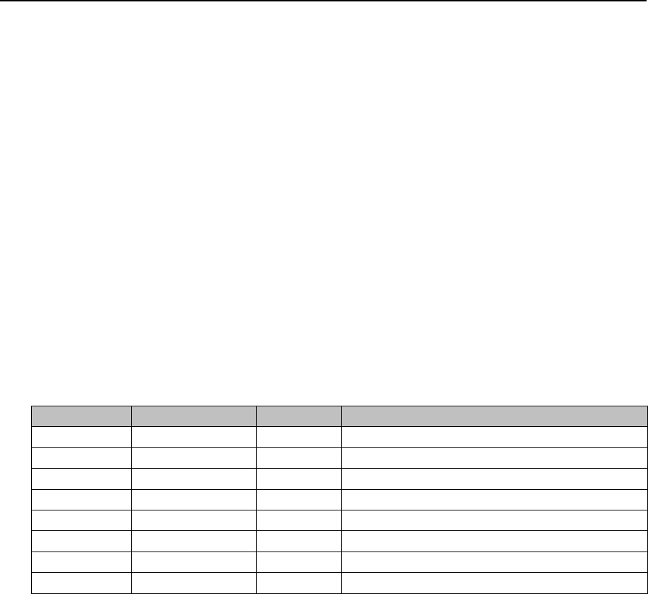
Pinout: Refer to Table 17
Pin Signal Pin Signal
1 GPI0 2 GND
3 GPI1 4 GND
5 GPI2 6 GND
7 GPI3 8 GND
9 GPO0 10 GND
11 GPO1 12 GND
13 GPO2 14 GND
15 GPO3 16 GND
Table 22 Pinout GPIO connector
4.17 ATX Connector
An ATX connector with additional ATX12V connector is available to power the system.
Specification ATX connector:
References: X36
Connector: Molex 44206-0007
Pinout: Refer to ATX specification V2.2
[2]
Specification ATX12V connector:
References: X37
Connector: Molex 39-29-9042
Pinout: Refer to ATX specification V2.2
[2]