


CX-MB-EVA2 User's Manual Hardware
26
4.6.2 Backlight Inverter Interface
The supply voltage of the backlight can be adjusted with jumper JP0601. The according
position is printed on the PCB.
Jumper J5 should be set according to the backlight inverter used.
If the inverter needs a low active start signal, jumper J5 has to be set to L (pin1
connected to pin2).
If the inverter needs a high active start signal, jumper J5 has to be set to H (pin2
connected to pin3).
Brightness of the backlight inverter is controlled via the LVDS-BKLT-CTRL signal.
The LVDS-BKLT-CTRL signal of the COM Express module is a PWM signal with current
chipsets. This signal is integrated and then limited to the maximum allowable voltage of
the backlight inverter via a voltage divider.
Control voltage: 0...3V
A value of 0V corresponds to maximum brightness.
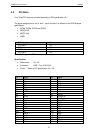
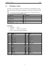
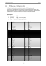
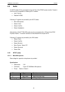
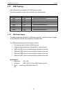
Specification:
References: X15
Connector: Molex (53047-0510) 53261-0590
Pinout: Refer to Table 5
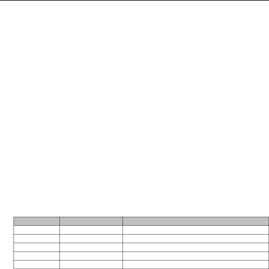
Pin Signal name Function
1 VCC Power supply backlight
2 GND Ground
3 BLON# Backlight On
4 VCON Brightness control
5 GND Ground
Table 10 Pinout Backlight