


12
1.3 A Typical Application
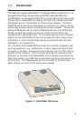
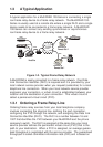
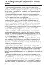
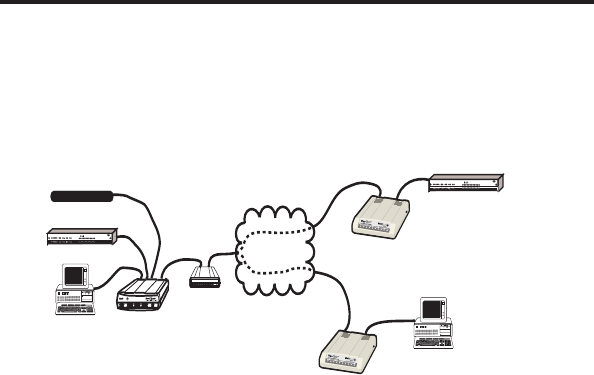
A typical application for a MultiFRAD 100-Series is connecting a single
non-frame relay device to a frame relay network. The MultiFRAD 100-
Series is usually used at a remote site where a single DLCI and a single
device needs to be connected to a frame relay network. A MultiFRAD
100-Series can connect any existing synchronous or asynchronous
non-frame relay device to a frame relay network.
Trunk
T1 DSU
Trunk
Host Site
Frame Relay
Network
17
16
26
27
T
e
c
h
Systems
®
Channel 1
Remote Site 2
Trunk
DTR
OH
Statistical Multiplexer
R
E
T
R
A
N
S
M
IT
1
2
3
BUFFER
FULLNESS
LEVEL
F
L
O
C
T
R
L
R
C
V
L
I
N
K
A
L
A
R
M
R
E
M
O
T
E
D
W
N
T
E
S
T
M
O
D
E
MultiMux
Internal Composite Link
MMH2834 CD RCV XMT CTS 28.8 24.0 19.2 14.4 OH TR EC DBUP
DSU CD RCV XMT CTS 56 19.2 RTS NS OOS TM
V29/V33 Modem CD RCV XMT CTS
External Composite Link
Channel Two Channel ThreeChannel Four
Command Modem
Channel Five
Channel SixChannel Seven
Channel Eight
XMTRCV XMTRCV XMTRCV
A
S
Y
N
C
L
I
N
K
5
6
K
D
S
U
V
2
9
/
V
3
3
RCV
Channel one
RCV
XMT
CD
RCV
XMT
CTS
V.35
XMTRCV
XMT
RCVXMTXMTRCV
XMT
RCV
INTERNAL LINK DEVICE
(Modems)
Systems
MultiTech
M
M
H
2
8
3
4
CD
MultiMux
Data
Remote Site 1
Data
PC
PC
Channel 2
DTR
OH
Statistical Multiplexer
R
E
T
R
A
N
S
M
IT
1
2
3
BUFFER
FULLNESS
LEVEL
F
L
O
C
T
R
L
R
C
V
L
I
N
K
A
L
A
R
M
R
E
M
O
T
E
D
W
N
T
E
S
T
M
O
D
E
MultiMux
Internal Composite Link
MMH2834 CD RCV XMT CTS 28.8 24.0 19.2 14.4 OH TR EC DBUP
DSU CD RCV XMT CTS 56 19.2 RTS NS OOS TM
V29/V33 Modem CD RCV XMT CTS
External Composite Link
Channel TwoChannel ThreeChannel Four
Command Modem
Channel Five
Channel SixChannel Seven
Channel Eight
XMTRCV XMTRCV XMTRCV
A
S
Y
N
C
L
I
N
K
5
6
K
D
S
U
V
2
9
/
V
3
3
RCV
Channel one
RCV
XMT
CD
RCV
XMT
CTS
V.35
XMTRCV
XMT
RCVXMTXMTRCV
XMT
RCV
INTERNAL LINK DEVICE
(Modems)
Systems
MultiTech
M
M
H
2
8
3
4
CD
MultiMux
LAN 1
Ethernet Network
Ethernet
MultiFRAD 100
MultiFRAD 100
MultiFRAD II
Figure 1-2. Typical Frame Relay Network
A MultiFRAD
is easily connected to a frame relay network. One Data
Link Connection Identifier (DLCI) is required and it is provided by your
local network service provider when you request (subscribe) for a local
telephone line connection. When your local network service provider
engineers your connection, a virtual circuit is established between your
location and the destination of your connection. This virtual circuit is
called a permanent virtual circuit (PVC).
1.3.1 Ordering a Frame Relay Line
Ordering frame relay services from your local telephone company
involves connecting the physical line, defining the port connection,
configuring the PVC through the network, and assigning the Data Link
Connection Identifier (DLCI). The DLCI is a number between 16 and
1007 that identifies the PVC between your MultiFRAD and the phone
company's switch. The DLCI is assigned at the same time your local
service provider defines the permanent virtual circuit (PVC) that is the
path to your destination. When a PVC is assigned, an average guaran-
teed throughput is negotiated with the service provider. The guaranteed
throughput is called committed information rate (CIR) and is based on