


Chapter 2 - Installation
Multi-Tech Systems, Inc. MT5634ZBA-Series User Guide 8
Chapter 2 - Installation
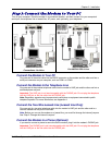
This chapter shows you step-by-step how to set up your Multi-Tech MT5634ZBA modem.
Safety Warnings
· Use this product only with UL- and CUL-listed computers (U.S.A. and Canada)
· To reduce the risk of fire, use only 26 AWG (.41mm) or larger telephone wiring.
· Never install telephone wiring during a lightning storm.
· Never install a telephone jack in a wet location unless the jack is specifically designed for wet
locations.
· Never touch uninsulated telephone wires or terminals unless the telephone line has been
disconnected at the network interface.
· Use caution when installing or modifying telephone lines.
· Avoid using a telephone during an electrical storm; there is a risk of electrical shock from lightning.
· Do not use a telephone in the vicinity of a gas leak.
Step 1: Mount the Feet
The modem comes with a set of self-adhesive plastic feet, which you can optionally mount on the modem.
To install the feet, simply peel them from their paper strip and press them into the recesses on the bottom of
the modem.
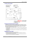
Step 2: Change the Internal Jumpers
This step is required only if:
· You intend to use the modem on a leased line.
· You intend to add a monophonic external speaker to your modem with the voice option. No changes
are needed for stereo.
This will require you to open the modem and move one or more jumpers on the modem’s printed circuit
board.
Warning: The following procedure must be performed by authorized service personnel.
Caution: The circuit board can be harmed by static electricity. Before you open the case, touch a grounded
object, such as the metal chassis of your computer, to discharge any static electricity in your body, then
touch the metal shell of the modem’s RS-232 connector to ensure that there is no voltage difference between
you and the modem.
Opening the Modem
1. If the modem is connected, turn it off and remove all connecting cables (including the power and
line cables).
2. Turn the modem upside down.
3. On the bottom of the modem are two screws, which hold the case together. Remove both
screws and set them aside.
4. Turn the modem right side up.
5. Remove the top part of the modem case.
6. To close the modem, reverse Steps 1–5.