


MultiVOIP FXS User Guide Mechanical Installation & Cabling
47
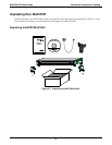
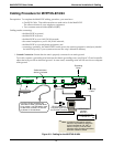
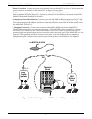
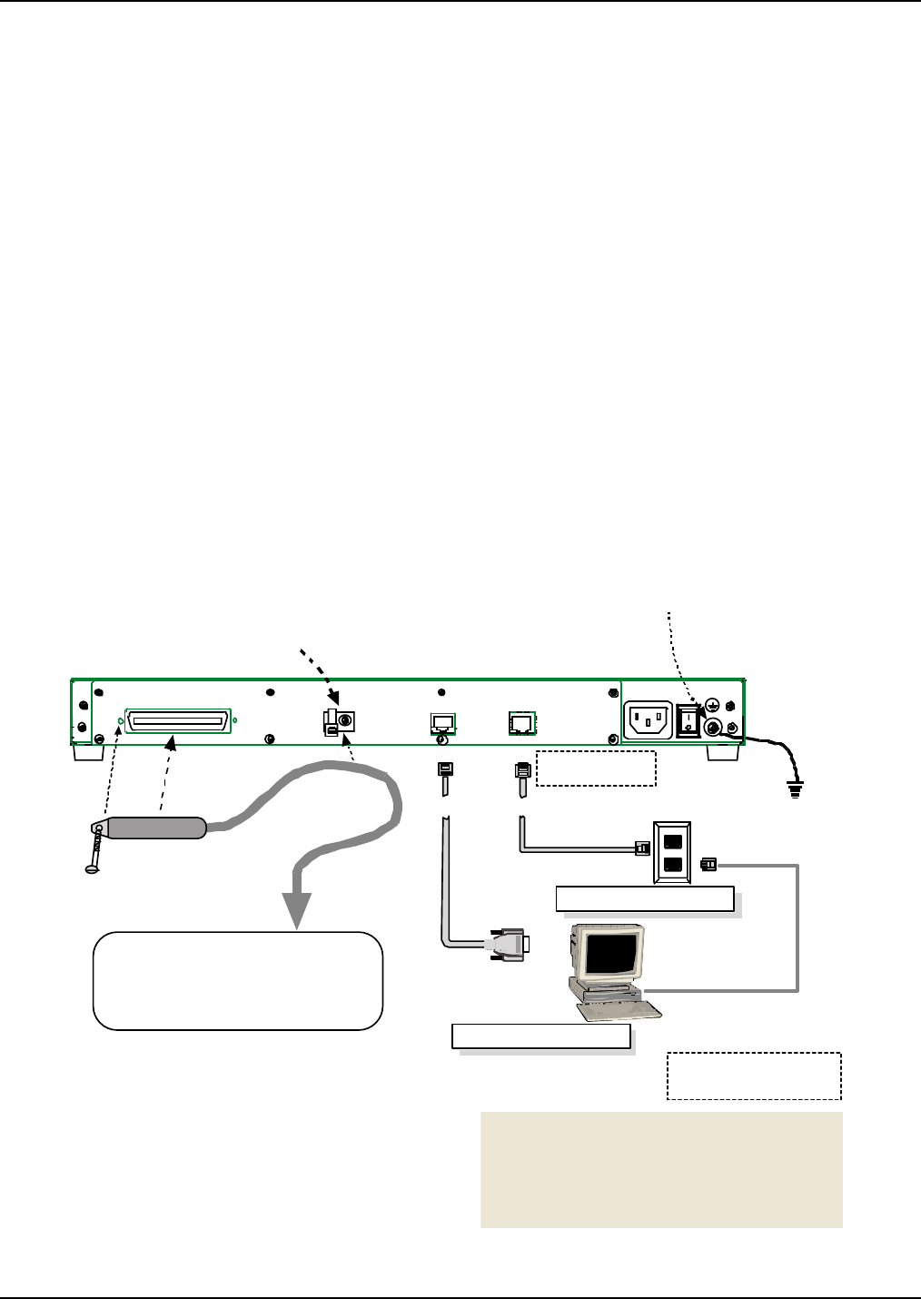
Cabling Procedure for MVPFXS-8/16/24
Prerequisites: To complete the MultiVOIP cabling procedure, you must have:
• One RJ-21 Cable. That cable must have a male end to fit the MultiVOIP.
The other end must fit your telephony equipment.
• Two common network cables (RJ45-to-RJ45).
Cabling entails connecting:
- the MultiVOIP to ground ,
- the MultiVOIP to power,
- the MultiVOIP to your LAN/WAN network,
- the control computer to your LAN/WAN network,
- the MultiVOIP to your telephone equipment, and
- connecting, optionally, the MultiVOIP Console port to the control computer’s serial port (needed
for initial setup only if your system cannot use the voip’s default IP address).
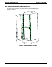
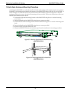
1. Ground Connection. Ensure that the unit is properly connected to an earth ground.
To do this, connect a grounding wire between the chassis grounding screw (see Figure 3-5) and a metallic
object that will provide an electrical ground. In some cases, mounting racks will can serve as an adequate
earth ground.
Console Port Connection
RJ-45
Connectors
Grounding
Screw
Grounding
Cable
DB-9 Connector to
Computer Serial Port
for Console Functions
WAN/Ethernet Connection
VOIP Control
through
Web GUI
Cable hold-down
device is included.
RJ-21
The RJ21 50-pin connector can
terminate in either a terminal block,
a key system, or a PBX station card.
In each case, it offers FXS service
to phones or fax machines.
Voip’s Default IP
= 192.168.2.1
Control Computer’s IP
= 192.168. 2. x
**
**
Note:
If network configuration makes it
difficult or impossible to assign the
control computer to 192.168.2.x,
then the voip’s IP must be reset
using the voip’s Console connection.
See
User Guide
for details.
CONSOLE WAN
TELECOM
25
1
25 1
50
50
26
26
Figure 3-5: Cabling for the MVPFXS-8/16/24