


Mechanical Installation & Cabling MultiVOIP FXS User Guide
48
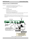
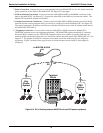
2. Power Connection. Connect the power cord supplied with your MultiVOIP to a live AC outlet and to the
power connector on the back of the MultiVOIP. See Figure 3-5 (top right).
3. VOIP-to-Network Connection. Connect a network cable (RJ45-to-RJ45) to the WAN connector on the
back of the MultiVOIP. See Figure 3-5. Connect the other end of the cable to your network switch. The
MultiVOIP’s default IP address is 192.168.2.1.
4. Computer-to-Network Connection. Connect a network cable (RJ45-to-RJ45) between your LAN/WAN
network and the control computer that you will use to configure/control the MultiVOIP. See Figure 3-5.
The control computer’s IP address must be set so that the first three octets of the IP address match that of
the MultiVOIP (192.168.2.x).
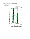
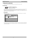
5. Telephony Connection. Connect a 50-conductor cable (RJ21-to-RJ21) between the MultiVOIP’s
TELECOM connector and your telephone equipment. The MultiVOIP requires a male RJ-21 connector.
Secure the RJ-21 connector to the TELECOM receptacle with a screw (which is typically built into the
connector) and use the hold-down device to secure the cable to the back panel of the MultiVOIP unit. See
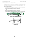
Figure 3-5. The gender of the RJ-21 connector on the other end of the cable must fit your telephony
equipment. Figure 3-6 shows some typical ways in which the other end of the RJ-21 cable might be
connected.
RJ-21
RJ-21
RJ-21
RJ-21
RJ-11
RJ-11
RJ-11
PBX
Station
Card
OR
OR
Key
Phone
System
Terminal
Block
to MVPFXS-8/16/24
unit
Figure 3-6: RJ-21 Cabling between MVPFXS unit and FXS phone equipment