


MultiVOIP FXS User Guide Mechanical Installation & Cabling
49
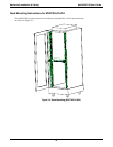
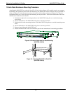
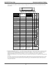
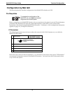
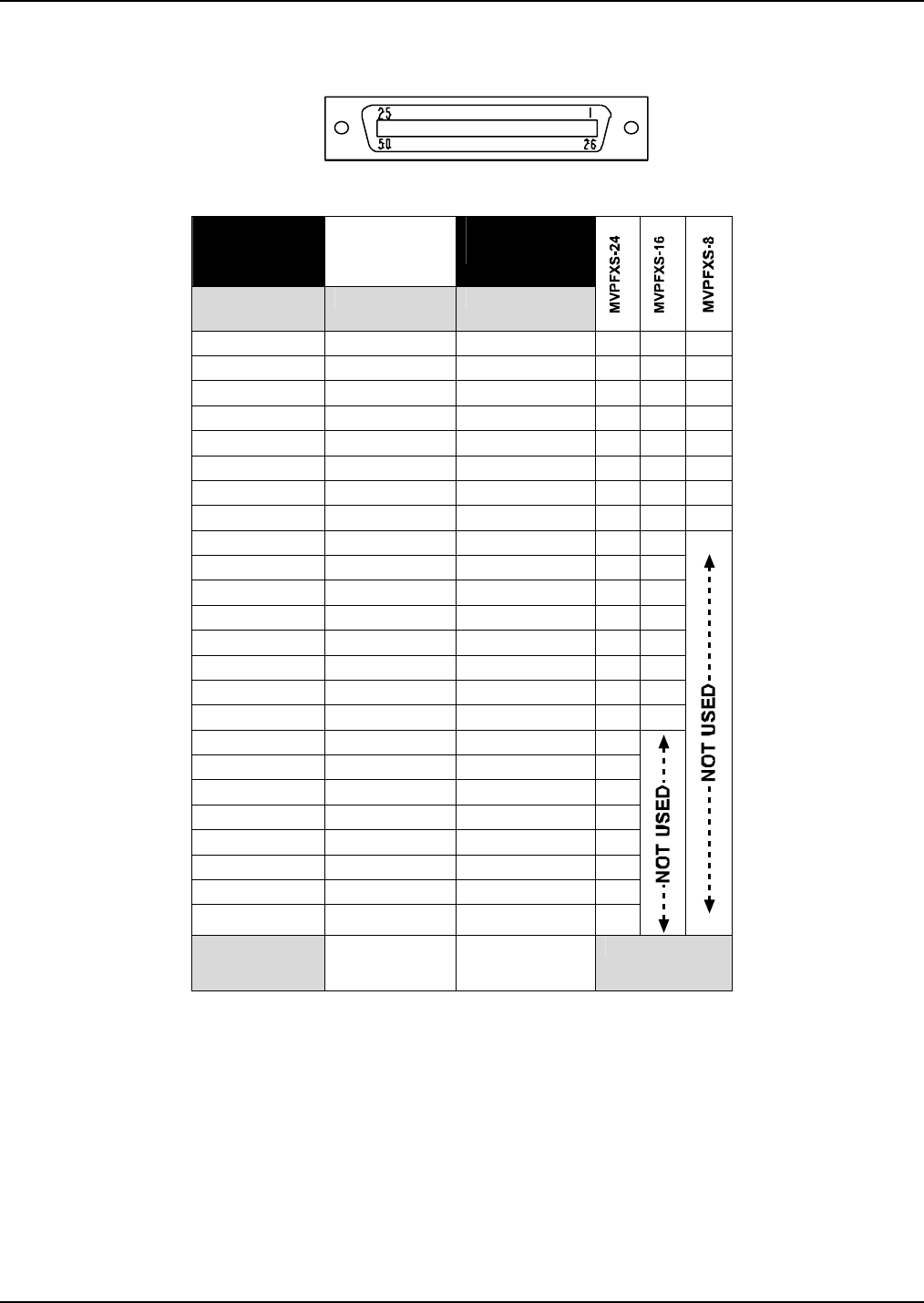
The footprint of the RJ-21 connector is shown in Figure 3-7 and its pin-out list is presented in the table
that follows.
Figure 3-7: RJ-21 Connector Footprint
RJ-21
Connector
Pin-Out List
TIP:
on Pins 1 – 24
RING:
on Pins 26 - 49
Wire Pairs for
Each Channel
Channel 1 1 26
√ √ √
Channel 2 2 27
√ √ √
Channel 3 3 28
√ √ √
Channel 4 4 29
√ √ √
Channel 5 5 30
√ √ √
Channel 6 6 31
√ √ √
Channel 7 7 32
√ √ √
Channel 8 8 33
√ √ √
Channel 9 9 34
√ √
Channel 10 10 35
√ √
Channel 11 11 36
√ √
Channel 12 12 37
√ √
Channel 13 13 38
√ √
Channel 14 14 39
√ √
Channel 15 15 40
√ √
Channel 16 16 41
√ √
Channel 17 17 42
√
Channel 18 18 43
√
Channel 19 19 44
√
Channel 20 20 45
√
Channel 21 21 46
√
Channel 22 22 47
√
Channel 23 23 48
√
Channel 24 24 49
√
Pin 25 is not
connected.
Pin 50 is not
connected.
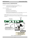
6. Console Connection (optional – not usually needed for initial setup). The Console Cable is needed at initial
setup only if your system cannot use the voip’s default IP address. In that case, the Console Cable is
needed to change the MultiVOIP’s IP address. Also, if, at a later date, you need to update the
MultiVOIP’s firmware, you will need to connect the Console Cable because it is required for that process,
as well.
If needed, connect the Console Cable (RJ45 male to DB9 female) between the MultiVOIP and the control
PC. Plug the RJ-45 end of the cable into the CONSOLE port of the MultiVOIP and the DB-9 end into a
serial port on the PC.