


MultiVOIP FXS User Guide Technical Configuration
69
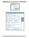
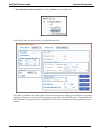
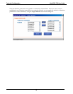
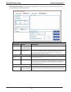
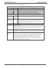
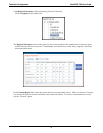
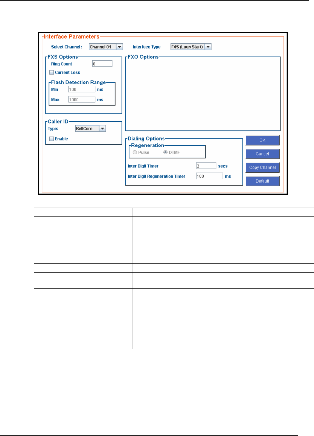
FXS Loop Start Parameters. The parameters applicable to FXS Loop Start are shown in the figure below
and described in the table that follows.
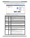
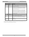
FXS Loop Start Interface: Parameter Definitions
Field Name Values Description
Select Channel 1-8 (MVPFXS-8);
1-16 (MVPFXS-16);
1-24 (MVPFXS-24)
Indicates the voip channel to which parameter values will be assigned.
Interface Type FXS Loop Start The value of this field determines whether this channel uses the FXS
Loop Start interface type or the FXO interface type. We are here
discussing the FXS Loop Start option.
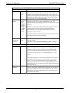
FXS Options fields
Ring Count ,
FXS
1-99
Maximum number of rings that the MultiVOIP will issue before giving
up the attempted call.
Current Loss Y/N
When enabled, the MultiVOIP will interrupt loop current in the FXS
circuit to initiate a disconnection. This tells the device connected to the
FXS port to hang up. The Multi-VOIP cannot drop the call; the FXS
device must go on hook.
Flash Detection Range fields
Min/Max for Min. and Max., 50
- 1500 milliseconds
For a received flash hook to be regarded as such by the MultiVOIP, its
duration must fall between the minimum and maximum values given
here.